Hi @vinny
Thank you for sending the Starling 2 Max STEP file, it's very helpful: the propellers are included, and the frame lines up exactly with the V3 model's coordinates.
The export is a single flattened body with no part names, so I can't identify individual components. I have a few questions about the ToF sensor in particular.
Configuration: Can you confirm this file is the V4 frame with the C29 sensor package?
ToF position: Where is the ToF sensor in this model? A centre point and the direction of the optical axis would be enough, in the file's own coordinates (X right, Y up, Z forward, mm). Comparing it with the V3/C28 model, my best guess is the front-left of the nose, standing upright, around X −13 / Y 10 / Z 63 mm. Is that right?
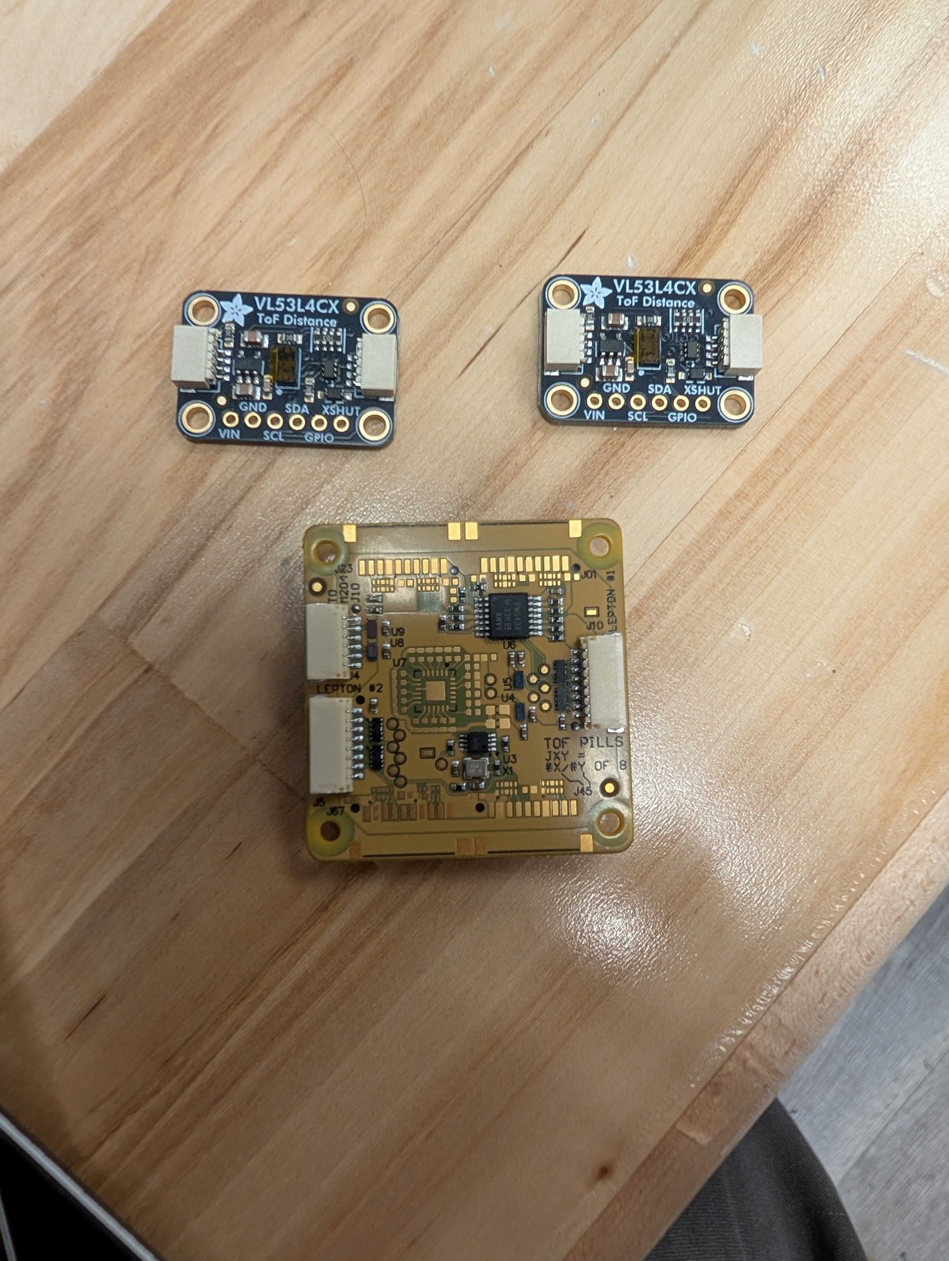
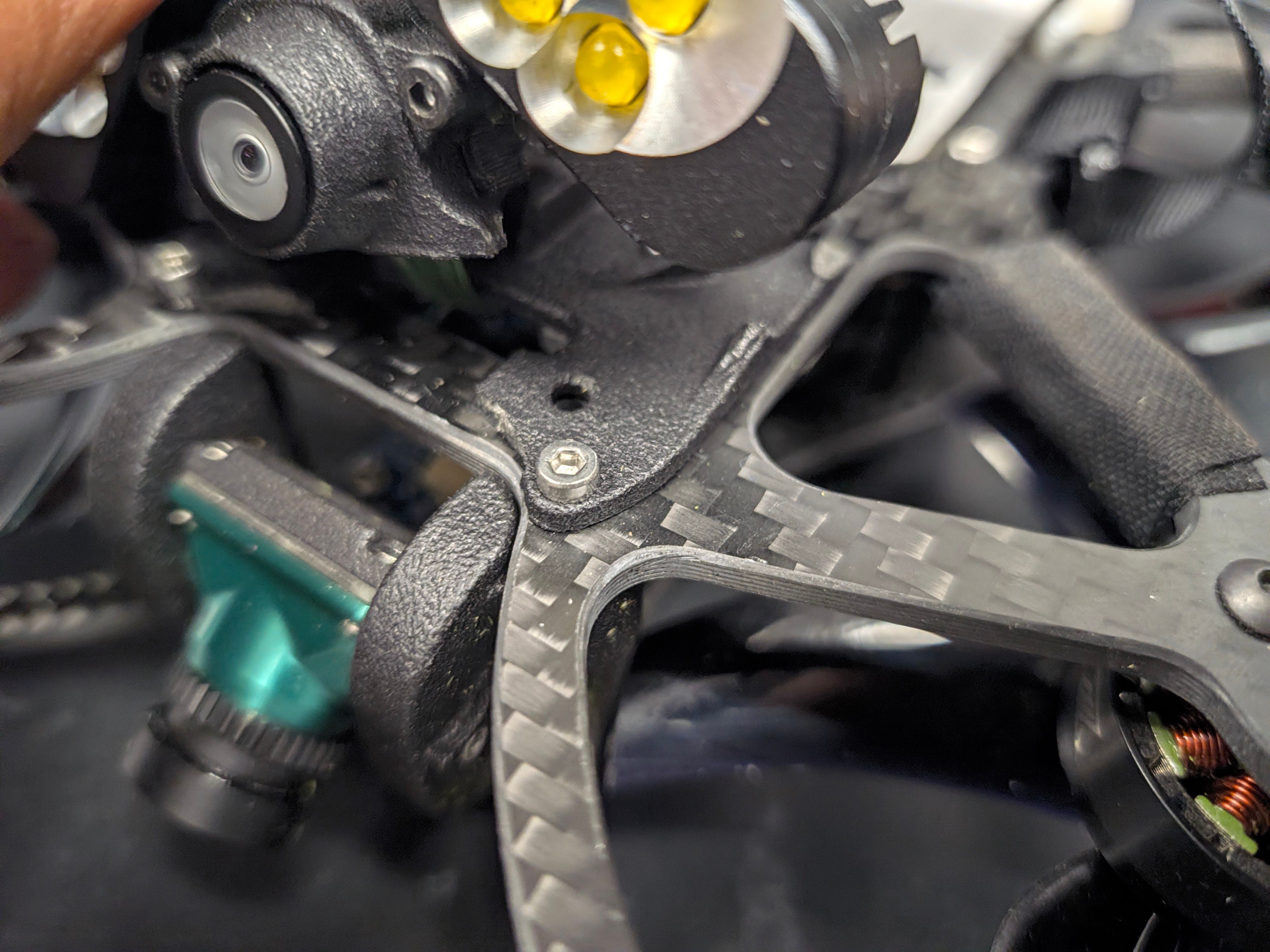
Which ToF parts: Which ToF module and adapter board does C29 use? I tried virtually fitting your public M0178_STARLING_TOF_ADAPTER_REVA and MCAM-00005-TOF-A65 3D models into the nose of this STEP file (software shape-matching, no physical hardware), and neither matches exactly. Is there a different part number, or is the ToF shown in simplified form in this export?
Orientation and field of view: An earlier forum post said the C29 ToF is mounted "vertically". Does that mean the 106° side of its 106° × 86° view is vertical, so the horizontal view is 86°?
Named-parts version: If possible, could you share the same model as a multi-part STEP with component names, or a dimensioned drawing of the C29 nose showing the ToF, tracking-camera and hi-res-camera positions?
I need this to check that a removable payload mount and propeller bumpers stay out of the ToF and tracking-camera views.
Thanks again.