ModalAI Forum
    • Categories
    • Recent
    • Tags
    • Popular
    • Users
    • Groups
    • Register
    • Login
    1. Home
    2. Alex Kushleyev
    • Profile
    • Following 0
    • Followers 11
    • Topics 0
    • Posts 1725
    • Best 89
    • Controversial 1
    • Groups 1

    Alex Kushleyev

    @Alex Kushleyev

    ModalAI Team

    91
    Reputation
    228
    Profile views
    1725
    Posts
    11
    Followers
    0
    Following
    Joined Last Online

    Alex Kushleyev Unfollow Follow
    ModalAI Team

    Best posts made by Alex Kushleyev

    • RE: ToF v2 keeps crashing because of high temperature

      @dlee ,

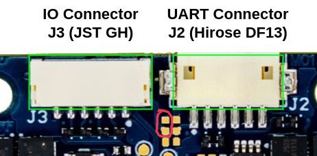
      Yes the new TOF sensor (IRS2975C) is more powerful that the previous generation. What I mean by that is that it can emit more IR power but also heats up more. Emitting more power allows the sensor detect objects at larger distances or objects that are not as reflective.

      In current operating mode, the auto exposure control is enabled inside the sensor itself, which modulates the emitted IR power based on the returns that the sensor is getting. That is to say, the power draw will vary depending on what is in the view of the sensor. If there are obstacles nearby, the output power should be low, otherwise it can be high. At full power, the module can consume close to 0.8-0.9W

      So the first solution, if design allows, is to add a heat spreader to dissipate the heat, which you already started experimenting with. The sensor has a large exposed copper pad in the back for heat sinking purposes for this exact reason. Just be careful not to short this pad to anything, use non-conducting (but heat transfering) adhesive pad between the sensor and heat spreader.

      In terms of a software solution to the issue, we can query the temperature of the emitter. We can also control the maximum emitted power used by the auto exposure algorithm. That is to say, still leave the auto exposure running in the sensor, but limit the maximum power that it is allowed to use.

      We are planning to add some software protection that limits the maximum output power as a function of the emitter temperature. This will require some implementation and testing.

      Meanwhile, please consider using a heat spreader, which will be the best solution if you want to make use of the full sensor's operating range and not have our software limit the output power in order to prevent overheating.
      posted in Image Sensors
      Alex KushleyevA
      Alex Kushleyev
    • RE: Propeller Coefficients for Starling V2

      Hello @Kashish-Garg-0

      we have a curve that is "motor voltage vs rpm", meaning that for a desired RPM, it tells the ESC what average motor voltage should be applied. The average motor voltage is defined as battery_voltage * motor_pmw_duty_cycle. The battery voltage in this curve is in millivolts. Since you are typically controlling the desired RPM, as a user you do not need to worry about what "throttle" or voltage to apply - the ESC does this automatically in order to achieve the desired RPM. this calibration curve is used as a feed-forward term in the RPM controller. The ESC does support an "open loop" type of control where you specify the power from 0 to 100%, which is similar to a standard ESC, but PX4 does not use that ESC control mode.

      By the way, you can test the ESC directly (not using PX4) using our voxl-esc tools (https://gitlab.com/voxl-public/voxl-sdk/utilities/voxl-esc/-/tree/master/voxl-esc-tools) which works directly on VOXL2 or a standalone linux PC (or mac). voxl-esc-spin.py has a --power argument where you specify the power from 0 to 100, which translates directly to the average duty cycle applied to the motor.

      Here is the calibration for the Starling V2 motor / propeller that we use:
      https://gitlab.com/voxl-public/voxl-sdk/utilities/voxl-esc/-/blob/master/voxl-esc-params/mavic_mini_2/mavic_mini_2.xml?ref_type=heads#L63

      Also, you can take a look at this post to see how to interpret those parameters a0, a1, a2 : https://forum.modalai.com/topic/2522/esc-calibration/2

      We also have some dyno tests for this motor / propeller : https://gitlab.com/voxl-public/flight-core-px4/dyno_data/-/blob/master/data/mavic_mini2_timing_test/mavic_mini2_modal_esc_pusher_7.4V_timing0.csv . We are not sure how accurate that is, but it can be used as a starting point. @James-Strawson can you please confirm that is the correct dyno data for the Starling V2 motors?

      Alex

      posted in Ask your questions right here!
      Alex KushleyevA
      Alex Kushleyev
    • RE: Sending Recorded Video Though Camera Server on VOXL2

      @reber34 , perhaps this approach can work for you:

      • record a video encoded at high bit rate (using voxl-camera-server and voxl-record-video . Please note that the output of voxl-record-video will not be in a standard container (such as mp4, etc), but you can fix it with ffpeg : ffmpeg -r 30 -i voxl-record-video.h264 -codec copy videofile.mp4
      • re-encode the video offline with desired codecs / bit rates / resolutions
      • install gst-rtsp-launch which uses gstreamer to set up an RTSP stream https://github.com/sfalexrog/gst-rtsp-launch/
        • you will first need to figure out what gstreamer pipeline to use on voxl2 that will load your video and parse the h264/h265 frames (can use null sink for testing) and then use that pipeline with gst-rtsp-launch which will take the encoded frames and serve them over rtsp stream.
      • gstreamer may be more flexible for tuning the encoding parameters of h264/h265 (compared to voxl-camera-server) and you can also use it in real time later (using voxl-streamer, which uses gstreamer under the hood)

      Another alternative is to use voxl-record-raw-image to save raw YUVs coming from voxl-camera-server and then use voxl-replay and voxl-streamer - the latter will accept YUVs from the MPA pipe and encode them using the bit rate that you want. Note that depending on the image resolution, YUV images will take a lot more space than encoded video, but maybe that is also OK since VOXL2 has lots of storage.

      Alex

      posted in Ask your questions right here!
      Alex KushleyevA
      Alex Kushleyev
    • RE: voxl_mpa_to_ros2 camera_interface timestamp

      @smilon ,

      I believe you are correct! Thank you. We will double check this and fix.

      posted in ROS
      Alex KushleyevA
      Alex Kushleyev
    • RE: UAV climbs out of control in POSITION mode (All QVIO sensors successfully calibrated)

      @rdjarvis , the cpu (by default) will run in auto mode, meaning it will slow down under light load. Can you try to set the cpu to performance mode using voxl-set-cpu-mode perf and see if your performance inproves?

      For front and rear stereo, which outputs for those cameras do you use? The code does debayering to mono and color for each camera, so disabling unneeded debayering can help.

      posted in PX4 Autonomy Developer Kit
      Alex KushleyevA
      Alex Kushleyev
    • RE: OV7251 RAW10 format

      Hello @Gicu-Panaghiu,

      I am going to assume you are using VOXL1, since you did not specify..

      We do have RAW8 and RAW10 support for OV7251. The selection of the format has to be done in several places.

      First, you have to select the correct camera driver, specifically..

      ls /usr/lib/libmmcamera_ov7251*.so
      /usr/lib/libmmcamera_ov7251.so
      /usr/lib/libmmcamera_ov7251_8bit.so
      /usr/lib/libmmcamera_ov7251_hflip_8bit.so
      /usr/lib/libmmcamera_ov7251_rot180_8bit.so
      /usr/lib/libmmcamera_ov7251_vflip_8bit.so
      

      there are 5 options and one of them is _8bit.so which means it will natively ouptput 8bit data (all others output 10 bit data).

      the driver name, such as ov7251_8bit has to be the sensor name <SensorName>ov7251_8bit</SensorName> in /system/etc/camera/camera_config.xml.

      You can check camera_config.xml for what sensor library is used for your OV7251.

      When you run voxl-configure-cameras script, it will actually copy one of the default camera_config.xml that are set up for a particular use case, and I believe it will indeed select the 8bit one - this was done to save cpu cycles needed to convert 10bit to 8bit, since majority of the time only 8bit pixels are used.

      Now, you mentioned that HAL_PIXEL_FORMAT_RAW10 is passed to the stream config and unfortunately this does not have any effect on what the driver outputs. If the low level driver (e.g. libmmcamera_ov7251_8bit.so) is set up to output RAW8, it will output RAW8 if you request either HAL_PIXEL_FORMAT_RAW8 or HAL_PIXEL_FORMAT_RAW10.

      So if you update the camera_config.xml to the 10bit driver and just keep the HAL_PIXEL_FORMAT_RAW10 in the stream config (then sync and reboot), you should be getting a 10 bit RAW image from the camera. But since the camera server is currently expecting 8 bit image, if you just interpret the image as 8 bit, it will appear garbled, so you will need to handle the 10 bit image (decide what you want to do with it) in the camera server.

      posted in Image Sensors
      Alex KushleyevA
      Alex Kushleyev
    • RE: VOXL ESC V1 or V2

      @wilkinsaf , M0027 was never shipped to any customers, as it was a test version of the ESC. So there should only be M0049, M0117, M0134 and M0129 (mini) ESCs out there. Like Vinny said, all of those ESCs have a blue status LED for each MCU.

      If your ESC has a larger rectangular shape (as opposed to a square), it could be a really old ESC (Atmel-based, not STM32-based), which we do not really support any more. I hope this helps!

      Alex

      posted in VOXL 2
      Alex KushleyevA
      Alex Kushleyev
    • RE: Cannot change TOF framerate

      The ipk is available here now : http://voxl-packages.modalai.com/stable/voxl-hal3-tof-cam-ros_0.0.5.ipk - you should be able to use the launch file to choose between two modes (5=short range and 9=long range) and fps, which are listed in the launch file.

      posted in Ask your questions right here!
      Alex KushleyevA
      Alex Kushleyev
    • RE: Onboard Image Processing using ROS + OpenCV (+ possibly some ML library in the future)

      @Prabhav-Gupta , yes it seems like OpenCV and ROS YUV_NV12 formats do not match up. I will take a look at it.. it seems the ROS YUV is packed (interleaved) while standard for storing YUV NV12 is having two planes : plane 1 : Y (size: widthheight), plane 2 : UV (size: widthheight/2)

      In the meantime.. you can stream a rtsp h264/h265 from VOXL (use decent quality so that image looks good) and use opencv to receive the stream and get decompressed images: https://stackoverflow.com/questions/40875846/capturing-rtsp-camera-using-opencv-python

      Would that work for you ? (unfortunately with rtsp stream, you will not get the full image metadata, like exposure, gain, timestamp, etc).

      RTSP streaming can be done using voxl-streamer, which can accept either a YUV (and encode it) or already encoded h264/5 stream from voxl-camera-server.

      Alex

      posted in ROS
      Alex KushleyevA
      Alex Kushleyev
    • RE: Poor GPS Fix

      @Rodrigo-Betances , yes, absolutely. I will provide your name to the team.

      posted in PX4 Autonomy Developer Kit
      Alex KushleyevA
      Alex Kushleyev

    Latest posts made by Alex Kushleyev

    • RE: Unresponsive polling from FPV Racing 4-in-1 ESC

      @shawn_ricardo , just to close the loop on the original issue.. the delay in the calibration procedure was caused by UART data or processing of the ESC feedback backing up. The fix is to just slow down the command rate, seen in this commit : https://gitlab.com/voxl-public/voxl-sdk/utilities/voxl-esc/-/commit/b512f9e3d5e695868775de3d40eedb2ad15cf6d9 . Additionally, using command line argument --cmd-rate 100 when you run the calibration script on VOXL2 will fix the issue.

      Regarding the issue in the step response where the feedback data appears not smooth, i believe it is related to FTID's buffer / delay. FTDI adapters have this parameter latency_timer which is 16ms by default, which amount of time the FTDI board holds the RX'ed data before passing forwarding it to the PC (and vice versa, i believe). You can set that value to 1:

      You can check this value:

      cat /sys/bus/usb-serial/devices/ttyUSB0/latency_timer
      

      And set it:

      sudo su
      echo 1 > /sys/bus/usb-serial/devices/ttyUSB0/latency_timer
      

      You would need to do this every time you unplug / plug the FTDI device back in.

      (note that this applies only to Linux PC, not VOXL2).

      Besides this, i think the plots look good. It looks like you have set the kp pretty low, which keeps the response softer (less chance of de-sync).

      Alex

      posted in Ask your questions right here!
      Alex KushleyevA
      Alex Kushleyev
    • RE: ESC calibration help

      @victochen , just to close the loop on the original issue.. the delay in the calibration procedure was caused by UART data or processing of the ESC feedback backing up. The fix is to just slow down the command rate, seen in this commit : https://gitlab.com/voxl-public/voxl-sdk/utilities/voxl-esc/-/commit/b512f9e3d5e695868775de3d40eedb2ad15cf6d9 . Additionally, using command line argument --cmd-rate 100 when you run the calibration script on VOXL2 will fix the issue.

      posted in Support Request Format for Best Results
      Alex KushleyevA
      Alex Kushleyev
    • RE: Flir Boson+ Issues on VOXL2 Mini

      @jonathankampia ,

      (just FYI we just updated some more information about M0201 / M0153 here : https://docs.modalai.com/M0153/)

      It seems that connection is not an issue in your case. However, the config file is not correct.

      Please use the minimum config, as provided in the Hadron setup docs. We will update the Boson setup with a minimum config as well.

      https://docs.modalai.com/voxl2-hadron/#minimum-config

      What is happening is that the ISP is not liking the custom resolution of the Boson (640x512) and it causes a low level buffer overrun, causing voxl to crash. So disabling small and large streams should fix it. use preview stream only and enable raw preview.

      Here is the config snippet from the above link:

      {
                "type": "boson",
                "name": "boson",
                "enabled":  true,
                "camera_id":    0,
                "fps":  30,
                "en_preview":   true,
                "en_misp":  false,
                "preview_width":    640,
                "preview_height":   512,
                "en_raw_preview":   true,
                "en_small_video":   false,
                "en_large_video":   false,
                "ae_mode":  "off"
            },
      

      (please note that after you run voxl-camera-server with this minimal config entry, the camera server will auto populate some additional fields). Also note that i did not paste the full config here, just the camera entry - a few more lines at the top and bottom (mostly braces) are misssing.

      I am going to add Boson support in our MISP processing pipeline so you will be able to get h264/h265 encoded boson video feed as well, but meanwhile you could just use voxl-streamer to encode these relatively small frames.

      Please let me know if the config update fixes your issue.

      Alex

      posted in Ask your questions right here!
      Alex KushleyevA
      Alex Kushleyev
    • RE: Incorrect battery0 voltage on QGC

      @george-kollamkulam , also are you able to use voxl-esc tools to verify the voltage?

      You can run the following command, which will not actually spin the motors, but will communicate with the ESC and receive feedback:

      #stop px4
      systemctl stop voxl-px4
      
      cd /usr/share/modalai/voxl-esc-tools
      ./voxl-esc-spin.py --id 255 --power 0
      

      The script should run and print out the voltage reported by the ESC.

      Alex

      posted in Ask your questions right here!
      Alex KushleyevA
      Alex Kushleyev
    • RE: Poor GPS Fix

      @somalley ,

      Very cool, thank you for sharing. We will try something like this.

      Please note that we have observed that the wifi dongle, which is right under the gps receiver, causes some interference as well. Can you please try to repeat your test by unplugging the dongle completely?

      A workaround to move the dongle to a different location is to use a different USB breakout board. Instead of M0141, use M0151 with a cable (JST GH to USB A Female).

      Alex

      posted in PX4 Autonomy Developer Kit
      Alex KushleyevA
      Alex Kushleyev
    • RE: M0138 FPV ESC capabilities

      @tonygurney , yes.

      Please see the comment about pin availability and pin numbers here : https://gitlab.com/voxl-public/voxl-sdk/utilities/voxl-esc/-/blob/master/voxl-esc-tools/voxl-esc-pwm.py?ref_type=heads#L17

      Please note that running voxl-esc-pwm.py script will use the serial port and cannot be done concurrently with PX4. This is a standalone tool, unlike voxl-send-esc-pwm-cmd tool, which sends a message to voxl-px4 and the pwm control message is then forwarded to the ESC by the voxl_esc px4 driver.

      Alex

      posted in ESCs
      Alex KushleyevA
      Alex Kushleyev
    • RE: Compatible ToF sensor setup with VOXL2 Mini

      @Luca-Zanatta , I believe your issue is that you are specifying the wrong type of TOF sensor. There are two types:

      • pmd-tof (old, EOL)
      • pmd-tof-liow2 (a.k.a irs2975c)

      Based on your sensor id (Slave Address: 0x007A, Sensor Id: 0x2975), you have pmd-tof-liow2, so you should run camera-server-config-helper tracking:ov7251:0 tof:pmd-tof-liow2:1).

      When you configured for pmd-tof, the camera server config was incorrectly set for the old TOF sensor, which has resolution of 224x1557. The new TOF sensor has resolution of 240x1629

      Please try. Sorry i did not catch that earlier.

      Alex

      posted in VOXL Accessories
      Alex KushleyevA
      Alex Kushleyev
    • RE: AR0144 RGB output on VOXL2

      @Jordyn-Heil , sorry for the delay.

      I will provide an initial example of getting 4 AR0144 streams into a standalone app and doing something with all of them on the GPU using OpenCL. This should be a nice example / starting point for multi-camera image fusion.

      Initially I will just use our standard mpa approach to get the image buffers from camera server to the standalone app. After that i will also try to do the same using the ION buffer support (which is already in camera server) which will allow us to map the buffers to GPU without doing any copy operations or sending image data over pipes. using ION buffer sharing will allow to further reduce the cpu and memory bandwidth usage, but it's still a bit of experimental feature and will need some more testing.

      Please give me a few more days.

      Alex

      posted in Image Sensors
      Alex KushleyevA
      Alex Kushleyev
    • RE: Hadron Boards to order

      @h3robotics ,

      Yes you should be able to test the Hadron on J8 using the instructions from the docs page (https://docs.modalai.com/voxl2-hadron/) -- just make sure you use Boson sensormodule 4 and ov64b sensormodule 5 (and camera IDs will still be 0 and 1 respectively, if there are no other cameras attached / detected).

      At this point you do not need to build a custom kernel, just need to use kernel variant 1 because it enables independent camera support on J8 which is needed for Hadron. Please note that you would not be able to use our standard ucoax camera on J8U because the camera reset signal is still not correctly patched through to J8 (which would require a kernel modificaiton). But in Hadron use case, camera reset is not used (both the IR and RGB camera are always on, so it happens to work out 🙂 ).

      I agree, it may be more convenient for you to switch to using the M0173 camera front end, so you can use a single kernel variant and also this would be a more future-proof approach.

      Alex

      posted in Image Sensors
      Alex KushleyevA
      Alex Kushleyev
    • RE: Poor GPS Fix

      @ROBERT-JUDD ,

      Yes, we are aware about the cable mismatch (sorry, the shipment was rushed a bit, but we will get it right!)

      Regarding the satellite SNR, yest it still looks low. I would normally expect 10dB higher.

      Are you able to test with disabled 5G modem? maybe pop out the 5G card or shut it down via a pin ( think we discussed how to do this long time ago).

      I just received the same kit and will be testing it today and compare with my initial implementation of the mast. Will report back..

      Alex

      posted in PX4 Autonomy Developer Kit
      Alex KushleyevA
      Alex Kushleyev