Please reach out here: https://www.modalai.com/pages/blue-uas-cleared-fpv-customer-intake-form
ModalAI Team
Private
Posts
-
Seeker User Manual -
VOXL2 + VOXL ESC FPV 4-in-1, voxl-suite 1.6.3 — battery_status never publishedOK, thanks for checking. maybe there was a typo before
-
VOXL2 + VOXL ESC FPV 4-in-1, voxl-suite 1.6.3 — battery_status never publishedNow that the main issue is resolved.. i am confused why the following test command did not work for you :
./voxl-esc-spin.py --id 255 --power 0The screenshot you posted had the command cut off -- are you sure you used the correct command? 255 is a special value that should spin all 4 ESCs: https://gitlab.com/voxl-public/voxl-sdk/utilities/voxl-esc/-/blob/dev/voxl-esc-tools/voxl-esc-spin.py?ref_type=heads#L190
Can you check if the
voxl-esc-spin.pyscript on your VOXL2 is the same as this file?Thanks!
Alex
-
On the Voxl2, the M0135 only recognizes the cameras on the JL connector, but not on the JU connector.It looks like I got this working. I modified the kernel to do the following
- not use the combo mode for J6L and allow using J6U as independent camera
- GPIO109 is used as a shared reset for cameras in slot 1 and 3 (because that's how the signal routing works on VOXL2 + M0135), so the kernel knows that this reset pin is shared
- this setup is not set up for camera sync - all cameras are running independently
- I have not tested any cameras in J8U, it may not work - but it should be possible to enable it, just need to test it.
You will need to update the kernel on your voxl2:
- https://storage.googleapis.com/modalai_public/temp/quad_ov7251_boson/qti-ubuntu-robotics-image-m0054-boot-quad-ov7251.img
- this kernel is based off the kernel that ships with SDK 1.6.3
- you can test it before overwriting the current kernel: https://docs.modalai.com/voxl2-kernel-build-guide/#test -- you should do to reduce the chance of bricking your VOXL2 (just in case)
HW Configuration:
- VOXL2
- four OV7251 plugged in to J6L. J6U, J7L, J7U via two M0135 adapters without any mods
- boson320 plugged into J8L via M0194 (you can use M0181 also)
- there are no shared CCI buses between the ov7251 cameras - slots 0-3 use CCI 0-3 respectively, so no CCI slave address conflicts
SW configuration
- appropriate sensormodules placed into
/usr/lib/camera/-- you can get them from/usr/share/modalai/chi-cdk/ov7251and../bosonfolders:
com.qti.sensormodule.ov7251_0.bin com.qti.sensormodule.ov7251_1.bin com.qti.sensormodule.ov7251_2.bin com.qti.sensormodule.ov7251_3.bin com.qti.sensormodule.boson_4.bin- use provided
voxl-camera-server.conf: https://storage.googleapis.com/modalai_public/temp/quad_ov7251_boson/voxl-camera-server-quad-ov7251-boson.conf- may need to modify your Boson resolution from
320x256to640x512if you you have Boson640
- may need to modify your Boson resolution from
Testing
- after you have all the cameras connected, boot using the test kernel
- test to see if all cameras are detected:
voxl-camera-server -l ... DEBUG: Cam idx: 0, Cam slot: 0, Slave Address: 0x00E2, Sensor Id: 0x7750 DEBUG: Cam idx: 1, Cam slot: 1, Slave Address: 0x00E2, Sensor Id: 0x7750 DEBUG: Cam idx: 2, Cam slot: 2, Slave Address: 0x00E2, Sensor Id: 0x7750 DEBUG: Cam idx: 3, Cam slot: 3, Slave Address: 0x00E2, Sensor Id: 0x7750 DEBUG: Cam idx: 4, Cam slot: 4, Slave Address: 0x00D4, Sensor Id: 0x00FF ...- start voxl-camera-server
- inspect sterams:
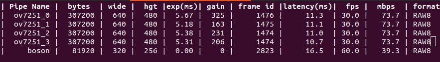
voxl-inspect-cam ov7251_0 ov7251_1 ov7251_2 ov7251_3 boson
Please give it a shot and let me know if it works!
Alex
-
VOXL2 + VOXL ESC FPV 4-in-1, voxl-suite 1.6.3 — battery_status never publishedI think you need to keep BAT1_SOURCE set to 0.
-
VOXL2 + VOXL ESC FPV 4-in-1, voxl-suite 1.6.3 — battery_status never publishedThis is what Codex says:
The root cause is a PX4 source-enum bug, not the ESC, baud rate, or VOXL_ESC_PUB_BST.

  - The supplied parameters select BAT1_SOURCE=2, meaning “ESCs”: /home/modalai/development/log_debug/no-batt-status/
    vehicle.params:5.

  - But voxl_esc constructs its battery object as BATTERY_SOURCE_POWER_MODULE (0): src/drivers/actuators/voxl_esc/
    voxl_esc.cpp:51.

  - The battery library publishes only when the driver’s source equals BAT1_SOURCE: src/lib/battery/battery.cpp:172.
  - Therefore 0 != 2, and every battery report is silently suppressed.

  This matches all the evidence:

  - VOXL_ESC_PUB_BST=1.
  - All four M0138 channels, including current-sensing ID 2, communicate at 2 Mbaud: /home/modalai/development/log_debug/no-
    batt-status/output.txt:279.

  - The flight log contains 232,935 healthy esc_status samples but no battery_status.
  - The forum test showed ID 2 reporting BOARD_VOLTAGE and BOARD_CURRENT, proving the ESC produces the special telemetry
    packet. This is the expected M0138 behavior documented in the ModalAI ESC FAQ (https://docs.modalai.com/voxl-escs/faq/).

  The proper code fix is one line:

  _battery(1, nullptr, _battery_report_interval,
           battery_status_s::BATTERY_SOURCE_ESCS)

  As an immediate workaround with the existing binary, set BAT1_SOURCE to Power Module (0), leave POWER_MANAGER=none, restart
  voxl-px4, and check:

  px4-listener battery_status 5

  That should publish, although the resulting topic will incorrectly identify its source as a power module. The one-line source
  change is the permanent fix.
Can you try setting that parameter and see if it works?
-
VOXL2 + VOXL ESC FPV 4-in-1, voxl-suite 1.6.3 — battery_status never publishedFile:
output.txt -
VOXL2 + VOXL ESC FPV 4-in-1, voxl-suite 1.6.3 — battery_status never publishedI sent an email to the address you have linked to this account.
-
VOXL2 + VOXL ESC FPV 4-in-1, voxl-suite 1.6.3 — battery_status never publishedOkay, shoot, let me see if we can get that fixed.
-
VOXL2 + VOXL ESC FPV 4-in-1, voxl-suite 1.6.3 — battery_status never publishedThe forum won't let you attach it in your reply?