ModalAI Forum
    • Categories
    • Recent
    • Tags
    • Popular
    • Users
    • Groups
    • Register
    • Login
    1. Home
    2. Jacob
    • Profile
    • Following 0
    • Followers 0
    • Topics 0
    • Posts 7
    • Best 0
    • Controversial 0
    • Groups 1

    Jacob

    @Jacob

    ModalAI Team

    0
    Reputation
    7
    Profile views
    7
    Posts
    0
    Followers
    0
    Following
    Joined Last Online

    Jacob Unfollow Follow
    ModalAI Team

    Latest posts made by Jacob

    • RE: Clarification on Starling2 (C27) Specifications and Propeller Compatibility

      @coreyazion Hello!

      Thank you for reaching out, I have some of this information and have asked relevant parties to gather the rest.

      We have a detailed CAD Model available to download for the Starling 2, which is referenced near the bottom of that Datasheet. You can hide and show any of the components at will to get exact measurements in any configuration you create for it.

      Center to center for motors is 132mm length, and 176mm width. The props themselves will cause it to be larger. The props are about 60mm long (from center of screw) and are themselves about 7.5mm away from the center of the motor to center of the prop mounting screw. So with props fully extended, the total length x width would be 267mm x 311mm. Height is about 86mm, from the top of the GPS hoop to the bottom of the feet.

      Folded up and with the prop retainers on, it is 154.200mm x 198.200mm x 86.279mm.

      I have reached out for: Maximum Speed, Weight (with and without prop retainers), prop manufacturer.

      My best guess as to the weight being off by 5g is one of them measured with the prop retainers one, and one without. For flight, they come off and I believe would be the 280g. If in storage with them on, closer to the 285g.
      posted in Ask your questions right here!
      JacobJ
      Jacob
    • RE: Broken Landing legs CAD model and STL to print

      Hello,

      Sorry to hear about the crash. We have a collection of several CAD files (including the Starling lineup) available on our developer website, https://developer.modalai.com/. Sign up and accept the terms and conditions and you should be able to access the "Protected Downloads" folder, which includes said CAD models. As far as I am aware, the "Landing Gear" has remained relatively unchanged throughout the lifespan of the Starlings, so any of the Starling CAD models should include it (Excluding the Starling Max, which uses longer legs).

      The part that ships with the drone is a nylon based material, so if you have access to a nylon that would be most comparable. We have seen some users do well with TPU or PETG as well for self printed replacements of this part.

      Good luck!

      posted in 3D Models
      JacobJ
      Jacob
    • RE: Mechanical Integration

      @ayrric

      1. We currently use a mix of 4 and 5mm spacers (we have used threaded on older model drones, current ones utilize unthreaded).
      • 4mm are used on certain boards that connect to the underside of the Voxl, such as on the Starling 2 and Starling 2 Max.
      • 5mm are used on most B2B connections on the top side of a Voxl. This has been used on Sentinels and all Starling variants for the Wi-Fi or Modem boards.
      1. I personally am not overly familiar with the components to answer this with certainty, but can say that we do not use any additional heat sinking on Starling model drones. Drones such as a sentinel with an add-on board will have a small fan pre-installed, but that is standard with the base model and on the other side of the board. We do have a small heat sink included with the ToF assembly on Starling 2 and Starling 2 Maxes.

      2. If you are referring to the Starling 2 Image Sensor Adapter, then it can be done in a variety of ways. Our current production process involves connecting the coax to both the image sensors the adapter board before installed to the Voxl 2. In some instances, we do use a bit of foam to secure some of them in place to prevent accidental release. (However, this is primarily a concern with the ToF flex cable, and not the mechanically held in place coax connectors.)
        We do also use a little bit of ESD safe tape (Kapton) to hold down some of the thin errant coax wires to prevent them from being pinched in the process of connecting the two boards.
        These coax connectors are fairly robust once installed but only rated for (as far as I am aware) roughly 30 connection cycles. So regardless of how or when you choose to install them, take caution in having to do it repeatedly. As long as you provide careful and even pressure when installing them it should be okay.

      Hopefully that answered your questions well enough!

      posted in VOXL 2
      JacobJ
      Jacob
    • RE: 3D STEP file for Seeker GPS Mount

      @Devang-Dhake That is interesting, I was able to get the parts separated and uploaded. Here is a link to download a zip file containing an A and B stl.

      https://storage.googleapis.com/modalai_public/modal_drawings/Seeker_GPS_Mount.zip

      posted in 3D Models
      JacobJ
      Jacob
    • RE: 3D STEP file for Seeker GPS Mount

      @Devang-Dhake Sorry for the late rely, I don't currently have a Solidworks installation on my computer but the steps outlined here should be sufficient to aid in splitting it up within Solidworks. The .step file consists of a single part with multiple bodies, which should be able to be exported individually if that is what your installation of Cura requires.

      posted in 3D Models
      JacobJ
      Jacob
    • RE: 3D STEP file for Seeker GPS Mount

      @Jacob

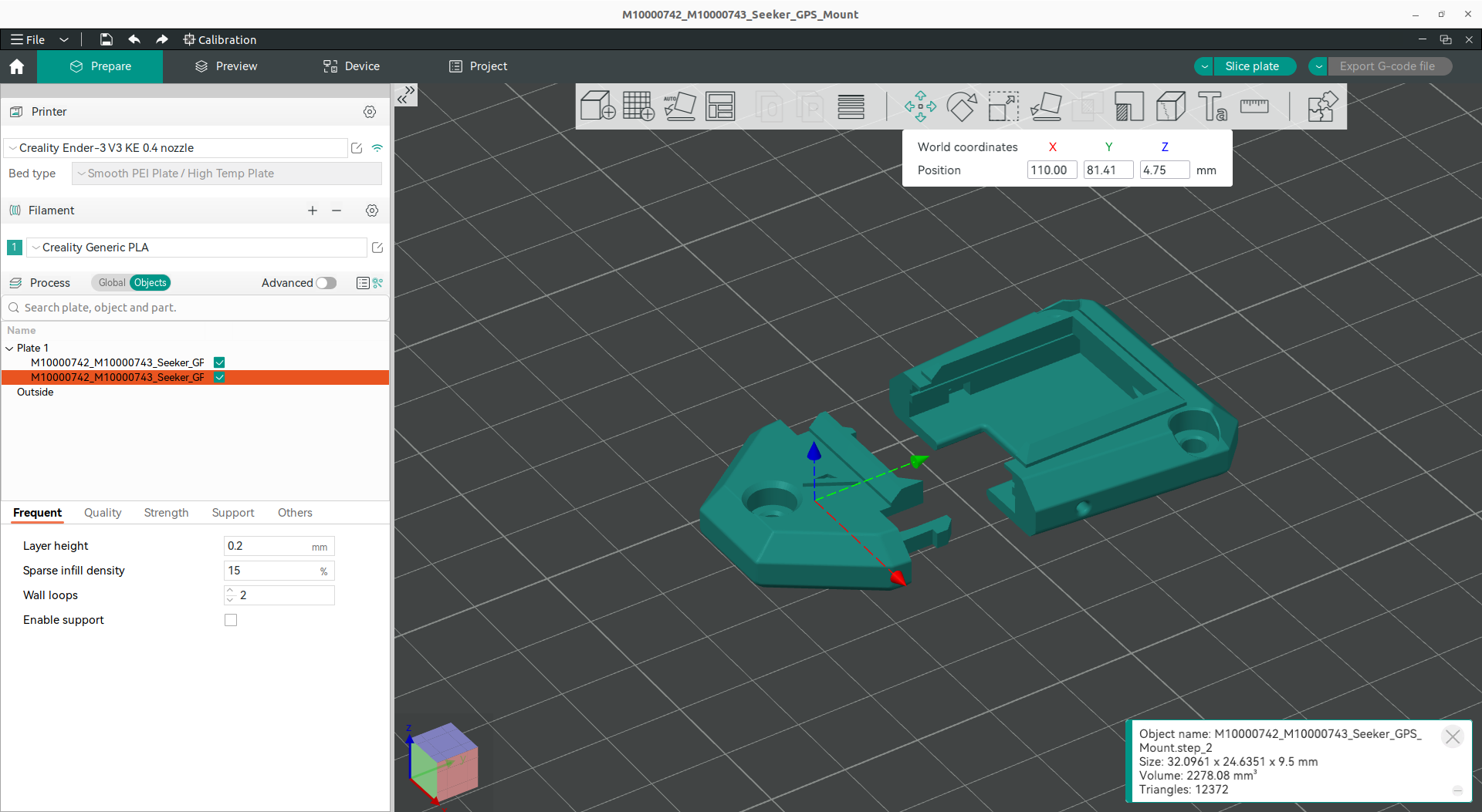
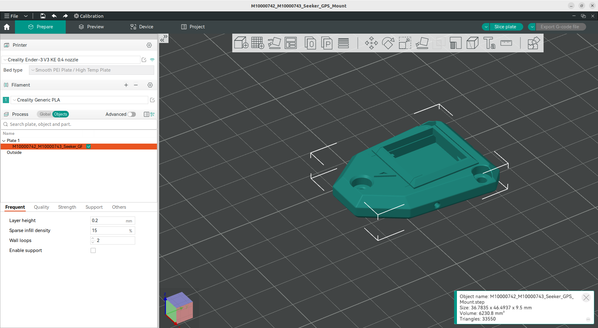
      As an example within a popular slicer, "Orca Slicer" this is how it shows up initially and after using a command to separate it.

      Screenshot from 2024-05-17 10-56-31.png

      Screenshot from 2024-05-17 10-55-23.png

      Screenshot from 2024-05-17 10-56-48.png

      Screenshot from 2024-05-17 10-58-41.png

      posted in 3D Models
      JacobJ
      Jacob
    • RE: 3D STEP file for Seeker GPS Mount

      Hello,

      This model is a .step, which will show up as multiple bodies/components within CAD software (Fusion, Solidworks, etc...) but in most slicers will show up as a single unit if not separated previously or with tools within the slicer. Some current slicers have the ability to read the individual bodies within a .step and separate them as desired.

      Which slicer and printer are you using? It may have this feature and save you time. If I am familiar with it I should be able to walk you through the process.
      If you utilize a CAD program, that would also enable you to read the file properly as multiple bodies and save/export each as the file type compatible with your slicer.

      If none of these options are available I can start the process of getting pre-separated STL/step files placed into a zipped folder for you to try.

      posted in 3D Models
      JacobJ
      Jacob