For the past two years, I've made a living designing and integrating VOXL2-based systems for clients across Europe. In many cases, I've demonstrated autonomous flight capabilities to customers only to later recommend that they move away from the platform. I've even rebuilt equivalent systems at roughly 30–40% of the cost while delivering many of the same capabilities and, in some cases, a more reliable development experience.
Ironically, a significant portion of my business exists because of the problems I've had to solve within the VOXL2 ecosystem.
If you're considering VOXL2 for research or commercial work, I would strongly encourage you to carefully evaluate the platform before committing to it. Until ModalAI demonstrates a stronger commitment to documentation, software quality, hardware quality control, and customer support, I believe there are better alternatives for most developers.
The following are the most consistent issues I've encountered.
1. Outdated and Incomplete Documentation
Much of the documentation is outdated, incomplete, or simply incorrect. This creates a frustrating development experience where AI language models, developers, and even experienced robotics engineers are all relying on inaccurate information—not because the tools are wrong, but because the official documentation is.
The result is wasted engineering time, unnecessary debugging, and teams losing confidence in otherwise competent engineers who end up chasing problems that originate from incorrect documentation rather than their own mistakes.
2. Quality Control Problems
I've encountered multiple instances of hardware being shipped with incorrect labeling or configuration. The most surprising example was ESC boards intended for 4S batteries being labeled as 6S versions, and vice versa.
Mistakes of this nature should never pass quality control.
What was even more disappointing was the response. Rather than issuing a recall or offering replacements, I was effectively told to live with the problem. I shared that experience with my clients, and it ultimately contributed to the cancellation of an order for ten additional units. Poor customer support doesn't just damage individual relationships—it costs future business.
3. Weak Peripheral Ecosystem
The surrounding hardware ecosystem feels underdeveloped for a premium platform.
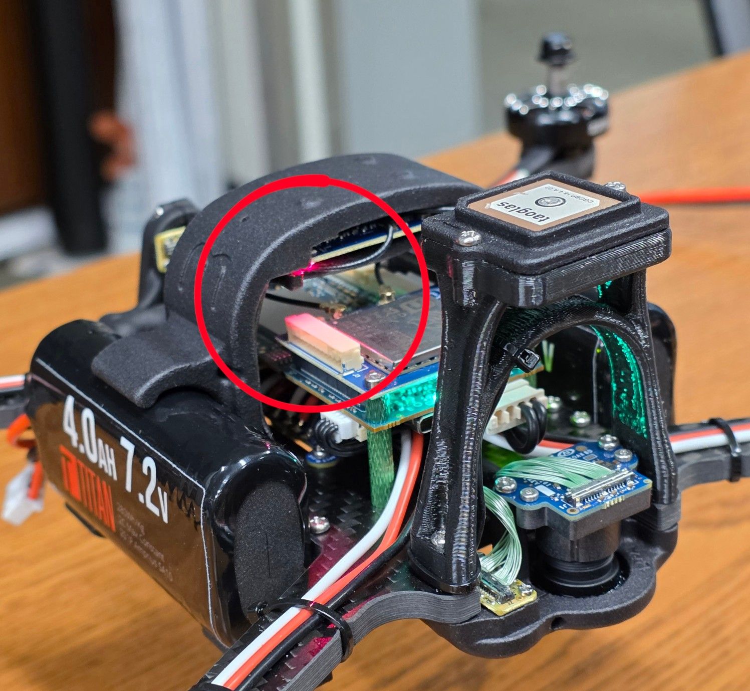
GPS shielding is inadequate, and many of the peripherals appear to be low-cost outsourced components with inconsistent quality. Signal integrity and EMI-related issues occur far more frequently than they should at this price point.
4. Thermal Design and Open-Source Accessibility
One of the more surprising design decisions is that the Qualcomm compute board ships without active cooling.
The apparent assumption is that propeller wash during flight will provide sufficient airflow. That may be true under ideal conditions, but it overlooks how many developers actually use the platform. Bench testing, indoor development, simulation, calibration, and autonomous software development often involve long periods where the aircraft is powered but stationary. I have a fan blowing into it but the device needs to have a cpu fan anyway.
Developers coming from more traditional PX4 companion computer architectures also don't expect CPU temperatures to directly influence flight performance, because those systems typically separate the flight controller from the companion computer. On VOXL2, thermal throttling can become part of the flight stack's behavior, which is not obvious to new users.
Compounding this issue is the difficulty of navigating ModalAI's platform-specific source code. While ModalAI works closely with PX4, locating and understanding the relevant code paths is far more difficult than it should be. This makes debugging platform-specific behavior unnecessarily time-consuming.
5. Confusing Feature Organization
Several features behave in ways that are poorly documented or unintuitive.
A common example is Vision Hub, where enabling certain functionality can unexpectedly cause the aircraft to fly a figure-eight trajectory as on by default. While there may be technical reasons for this behavior, they are not communicated clearly enough, leaving many users wondering whether they have misconfigured the system. Because a take off leads toe a fly away which makes the user think the PX4 paramers are incorrect when really they just left a demo code on in their system.
6. Non-Standard ESC Calibration
The VOXL ESC calibration process differs significantly from standard PX4 workflows.
As a result, it is often unclear whether calibration has completed successfully or whether changes have actually propagated through the PX4 stack. This ambiguity complicates troubleshooting and increases development time.
7. Excessive Platform-Specific Customization
ModalAI has introduced a significant number of custom modifications to the PX4 ecosystem.
While customization isn't inherently bad, many of these changes make the platform harder to understand, maintain, and debug. Instead of benefiting from the familiarity of standard PX4 workflows, developers frequently have to learn ModalAI-specific behaviors that add complexity without delivering proportional value.
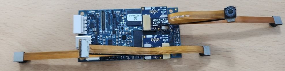
8. Proprietary Cable Ecosystem
The shielded 22-pin coax FFC cables are sold without publicly available pinout documentation.
As a result, customers are forced to purchase expensive replacement cables instead of fabricating or repairing what is, in reality, a relatively inexpensive component. Publishing the pinout would save customers time and money without negatively impacting the platform.
I could continue, but these are the recurring issues I encounter across professional deployments.
If your goal is to make meaningful progress in research or commercial development, I believe most teams are better served by alternative platforms. If you choose to use VOXL2, I would recommend limiting it to the areas where it genuinely excels—primarily as a companion computer for its four-camera multiplexer and out of the box deployment of open vins. That is their business moat and for the drones mentioned above I spent 80% of my time having to do charge the client to solve this problem. The difference is i use parts at 50% the cost and make profit because I spend more time listening to the needs of my client and fostering relationship with other companies to foster a collaborative environment in the ecosystem of engineering development.
Even then, I'm not convinced it represents good value. The weight savings rarely justify the cost, particularly as newer, lighter companion computers continue to emerge with more open software stacks, better documentation, and a significantly more developer-friendly ecosystem.
None of these criticisms are impossible to fix. Most are engineering, documentation, or customer support issues rather than fundamental hardware limitations. However, until those issues are addressed, I find it difficult to recommend VOXL2 for anything beyond niche use cases.
EMI Shielding on the device is very poor. This is by design