
FLIR LEPTON 3.5 Thermal camera with VOXL 2
-
@Vinny @Alex-Kushleyev
Thank you for your invaluable feedback on the previous design. I have thoroughly reviewed your input and subsequently updated the schematic to incorporate the suggestions, specifically regarding the integration of an I2C GPIO expander. The updated schematic is attached for your review.During recent debugging, I observed a critical issue: the Lepton module is not powering up, and no shutter sound is audible. This suggests a fundamental problem with power delivery or clocking to the module, which is currently preventing any functionality.
Concurrent to addressing this critical power-up issue, I would appreciate your expert insights on a few points concerning the updated design of the I2C GPIO expander and Lepton module interfacing:
-
I2C Bus Configuration: Regarding the I2C bus, should the I2C lines be connected in parallel to both the Lepton Module and the I2C GPIO expander?
-
Lepton Reset/Power Down Pins: Concerning the Lepton Module's RESET_N and POWER_DOWN_N pins, should the existing resistor-capacitor (RC) network connected to the RESET_N pin be retained, or can it be omitted?
-
I2C GPIO Expander INT Pin: For the I2C GPIO expander, is it permissible to leave the INT (Interrupt) pin unconnected, or does it require termination?
-
I2C GPIO Expander Software Configuration: From a software perspective, is the I2C GPIO expander a plug-and-play component, or does it require specific configuration?
Your guidance on both the immediate power-up challenge and the schematic queries would be greatly appreciated.
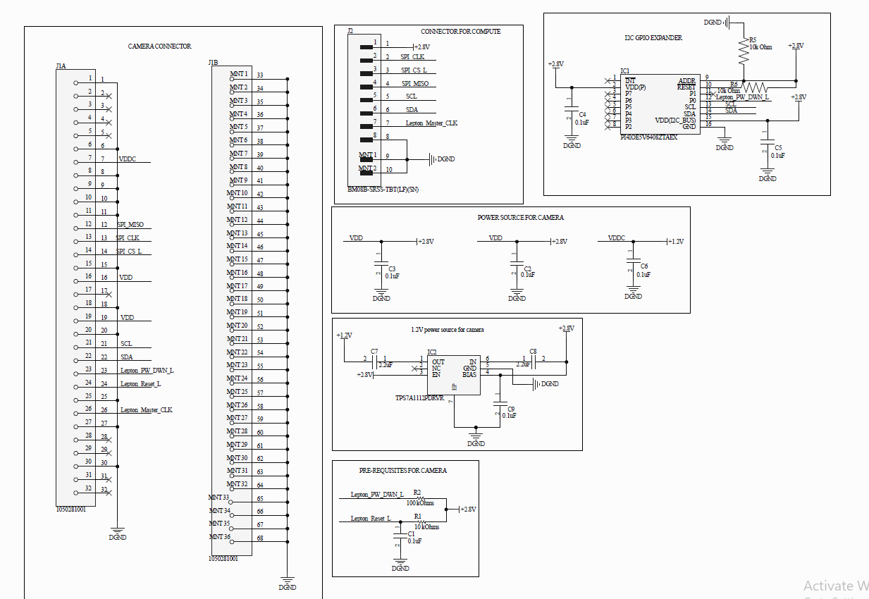
Thanks.
Hi @Jetson-Nano
Happy to continue helping.
Regarding your updated design first:
"I2C Bus Configuration: Regarding the I2C bus, should the I2C lines be connected in parallel to both the Lepton Module and the I2C GPIO expander?"
-- Yes.
"Lepton Reset/Power Down Pins: Concerning the Lepton Module's RESET_N and POWER_DOWN_N pins, should the existing resistor-capacitor (RC) network connected to the RESET_N pin be retained, or can it be omitted?"
-- We do not have any RC delay on the reset line since it is all GPIO controlled.
"I2C GPIO Expander INT Pin: For the I2C GPIO expander, is it permissible to leave the INT (Interrupt) pin unconnected, or does it require termination?"
-- It is an output and we do not use it, so N.C. is fine
I2C GPIO Expander Software Configuration: From a software perspective, is the I2C GPIO expander a plug-and-play component, or does it require specific configuration?
-- It is supported at that HW address by default with voxl-lepton-server (I think that it what is called, Alex can correct me if I'm mistaken)
However, your updated SCH has a couple errors:
-
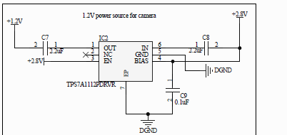
Your LDO input and output caps are not correctly done. They are in series, not shunts to GND as required:
-
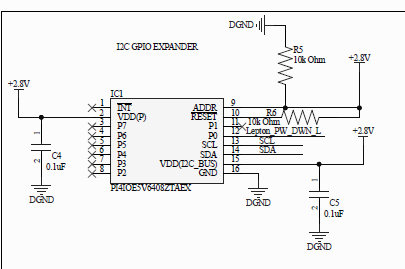
The Pull-down R on the GPIO expander is not correct. The ADDR pin will always be HIGH due to the direct connection to 2.8V, but our default is LOW (see the snippet from above):
-
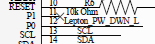
Also, the GPIO expander is meant to drive the RESET input of the Lepton, not the PWR_DWN input:
Now, as to your existing board not powering on, I have a clue for you...
Our very first lepton board we failed to notice the pin 1 hole in the Molex socket, and that is important since it sets a keying for the Lepton module. If the module is inserted incorrectly (90 or 180 off) it will clearly not power up. Pay close attention to the hole in the socket for pin 1 and two vs one slots in the socket which set the orientation.
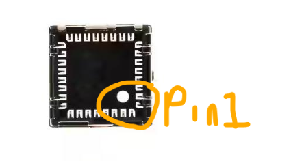
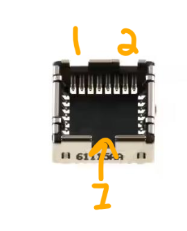
Keep us posted and hope this helped.
-
-
Hi @Jetson-Nano
Happy to continue helping.
Regarding your updated design first:
"I2C Bus Configuration: Regarding the I2C bus, should the I2C lines be connected in parallel to both the Lepton Module and the I2C GPIO expander?"
-- Yes.
"Lepton Reset/Power Down Pins: Concerning the Lepton Module's RESET_N and POWER_DOWN_N pins, should the existing resistor-capacitor (RC) network connected to the RESET_N pin be retained, or can it be omitted?"
-- We do not have any RC delay on the reset line since it is all GPIO controlled.
"I2C GPIO Expander INT Pin: For the I2C GPIO expander, is it permissible to leave the INT (Interrupt) pin unconnected, or does it require termination?"
-- It is an output and we do not use it, so N.C. is fine
I2C GPIO Expander Software Configuration: From a software perspective, is the I2C GPIO expander a plug-and-play component, or does it require specific configuration?
-- It is supported at that HW address by default with voxl-lepton-server (I think that it what is called, Alex can correct me if I'm mistaken)
However, your updated SCH has a couple errors:
-
Your LDO input and output caps are not correctly done. They are in series, not shunts to GND as required:
-
The Pull-down R on the GPIO expander is not correct. The ADDR pin will always be HIGH due to the direct connection to 2.8V, but our default is LOW (see the snippet from above):
-
Also, the GPIO expander is meant to drive the RESET input of the Lepton, not the PWR_DWN input:
Now, as to your existing board not powering on, I have a clue for you...
Our very first lepton board we failed to notice the pin 1 hole in the Molex socket, and that is important since it sets a keying for the Lepton module. If the module is inserted incorrectly (90 or 180 off) it will clearly not power up. Pay close attention to the hole in the socket for pin 1 and two vs one slots in the socket which set the orientation.
Keep us posted and hope this helped.
Thank you for your valuable feedback on the previous version of the schematic. Based on your recommendations, I have revised the design accordingly.
Please find the updated schematic attached below for your review
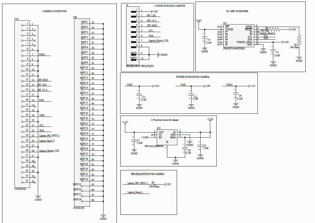
In addition to the design changes, I have also revisited the hardware setup to verify the power delivery, the Lepton module is still not powering up—there is no shutter sound or I²C response. At this point, I have exhausted the immediate troubleshooting steps and would greatly appreciate your guidance on further debugging strategies.
Could you please review the updated schematic and suggest any additional tests or possible points of failure that may have been overlooked?
Thank you again for your support and expertise.
-
-
Thank you for your valuable feedback on the previous version of the schematic. Based on your recommendations, I have revised the design accordingly.
Please find the updated schematic attached below for your review
In addition to the design changes, I have also revisited the hardware setup to verify the power delivery, the Lepton module is still not powering up—there is no shutter sound or I²C response. At this point, I have exhausted the immediate troubleshooting steps and would greatly appreciate your guidance on further debugging strategies.
Could you please review the updated schematic and suggest any additional tests or possible points of failure that may have been overlooked?
Thank you again for your support and expertise.
Hi @Jetson-Nano
Sch updates look correct. I'd still add a pull-up on the Lepton Reset to help control it during initial power-ON before the IO expander is configured.To help further debug your existing setup, I'd need more tangible info such as pictures with all your cables, etc. Do you have a DMM handy showing the voltages of 1.2V and 2.8V, and an O-scope for the 25MHz?
Can you also post a pic of your board without components installed (so I can review the layout as best as possible)?
It's hard to give much further guidance without actual hardware in my hands.
Thanks! -
@Alex-Kushleyev @Eric-Katzfey @modaltb
guys any help with solving this issue.
this the video feed I am getting.
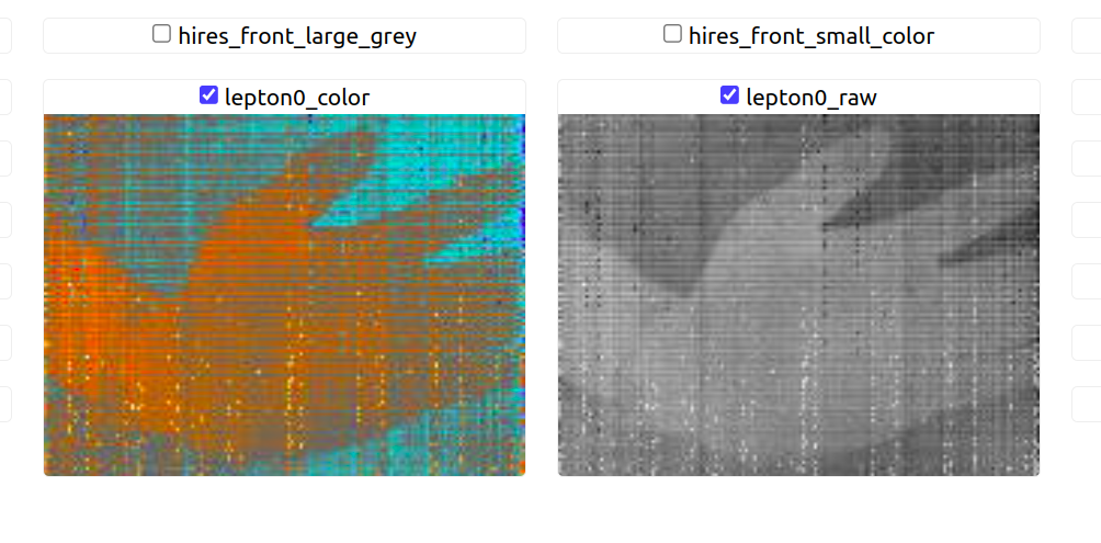
voxl2:~$ voxl-lepton-server ================================================================= spi_bus: 0 spi_speed: 16000000 en_i2c: 1 i2c_bus: 4 shutter_mode: manual flow_shutter_s: 20 closePeriodInFramesInAir: 0 openPeriodInFramesInAir: 1 desiredFfcPeriodMsInAir: 360000 desiredFfcTempDeltaCentiDegInAir: 600 assign_cpu_num: 7 en_timing_msg: 0 en_rotate: 1 ================================================================= existing instance of voxl-lepton-server found, attempting to stop it thread is now locked to the following cores: 7 attempting to init the io expander Attempting intitialization for M0188 (TCA9543A) ERROR: in voxl_i2c_read_bytes, failed to write to bus io_expander_init, failed to read TCA9543APWR control register If you are not using an M0188 lepton board then this is expected Attempting intitialization for M0187 (PI4IO) ERROR: in voxl_i2c_read_bytes, failed to write to bus io_expander_init, failed to read from io expander If you are not using an M0187 lepton board then this is expected attempting to open I2C CCI trying address 0x2a successfully opened I2C port Successfully connected to I2C CCI waiting for first frame from lepton to create MPA pipes creating MPA server pipes enabling MPA control interface client "voxl-portal78592109" connected to channel 0 with client id 0 client "voxl-portal64940239" connected to channel 1 with client id 0@Jetson-Nano did you ever figure out a solution to this? I'm getting similar imagery. Is this an FFC issue? Running the same breakout board on a raspberry pi produces completely normal imagery.
-
@Jetson-Nano did you ever figure out a solution to this? I'm getting similar imagery. Is this an FFC issue? Running the same breakout board on a raspberry pi produces completely normal imagery.
To close the loop here: we solved our issue of seeing lines by providing power to the lepton via one of the 3.3V pins on the voxl2 mini instead of relying on the power pin of J10 on the sparrow board.
-
To close the loop here: we solved our issue of seeing lines by providing power to the lepton via one of the 3.3V pins on the voxl2 mini instead of relying on the power pin of J10 on the sparrow board.
Hi @KLindgren
You raise a concern and something I will run by the team, but if you are powering the M0187 at 3.3V directly, you are violating the FLIR specs for the Lepton and our system design constraints.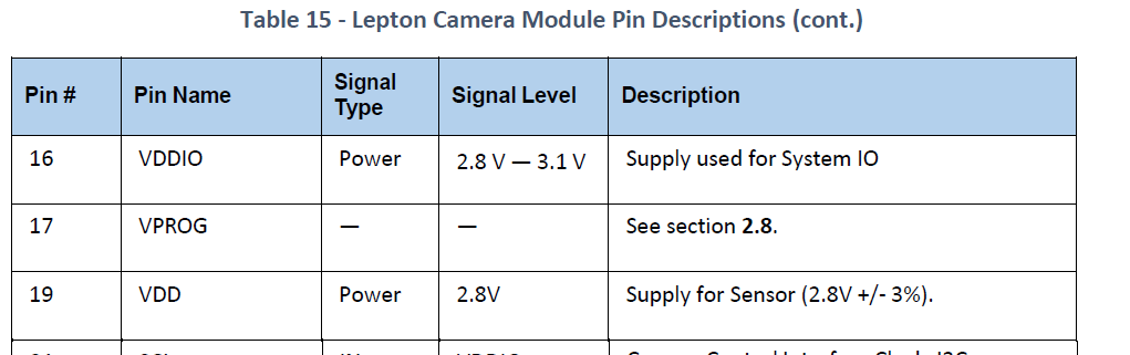
How are you connecting M0187 to M0188? Maybe your cable is introducing some extra losses giving you a lower than 2.8V supply?
-
Hi @KLindgren
You raise a concern and something I will run by the team, but if you are powering the M0187 at 3.3V directly, you are violating the FLIR specs for the Lepton and our system design constraints.How are you connecting M0187 to M0188? Maybe your cable is introducing some extra losses giving you a lower than 2.8V supply?
@Vinny apologies, I should have clarified we're using this PureThermal breakout board which regulates VIN from 3.3-5V
-
@Vinny apologies, I should have clarified we're using this PureThermal breakout board which regulates VIN from 3.3-5V
@KLindgren
OK, M0188 will not work with anything other than our M0187.
Thanks for clarifying. -
@KLindgren
OK, M0188 will not work with anything other than our M0187.
Thanks for clarifying.@Vinny said in FLIR LEPTON 3.5 Thermal camera with VOXL 2:
M0187
Hi @Vinny - I'm guessing the M0187 is your FLIR breakout board? Do you sell these?
-
@Vinny said in FLIR LEPTON 3.5 Thermal camera with VOXL 2:
M0187
Hi @Vinny - I'm guessing the M0187 is your FLIR breakout board? Do you sell these?
Hi @jared
Presently they are integrated within certain drones...
https://docs.modalai.com/stinger-vision-datasheet/I can poke the team to see if we can get it listed separately in the near future.
-
@Vinny apologies, I should have clarified we're using this PureThermal breakout board which regulates VIN from 3.3-5V
@KLindgren I am also using the same board but my video stream is with high disturbances, i have posted a image above in the chat. could you please share the image from your camera so that i could figure out what is wrong with my setup. Also the details of your setup, it would be of great help.
-
@KLindgren I am also using the same board but my video stream is with high disturbances, i have posted a image above in the chat. could you please share the image from your camera so that i could figure out what is wrong with my setup. Also the details of your setup, it would be of great help.
@Jetson-Nano our images looked the same as yours when providing power to the PureThermal from the sparrow board (m0188) but using a 3.3V from the voxl2 mini fixed the issue and gives us this imagery.
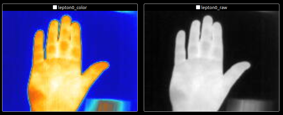
We are using power from the voxl2 mini's J19 and currently working on running 2 leptons with an RGB using the sparrow board.
-
@Jetson-Nano our images looked the same as yours when providing power to the PureThermal from the sparrow board (m0188) but using a 3.3V from the voxl2 mini fixed the issue and gives us this imagery.
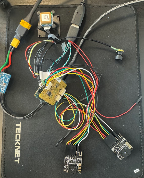
We are using power from the voxl2 mini's J19 and currently working on running 2 leptons with an RGB using the sparrow board.
@KLindgren thank you for reverting back. From which port are you taking the 3.3 V also how did you complete the circuit, the image you provide is confusing with respect to the connections, it would be great if you would provide further details.
-
Hi @jared
Presently they are integrated within certain drones...
https://docs.modalai.com/stinger-vision-datasheet/I can poke the team to see if we can get it listed separately in the near future.
-
@KLindgren thank you for reverting back. From which port are you taking the 3.3 V also how did you complete the circuit, the image you provide is confusing with respect to the connections, it would be great if you would provide further details.
@Jetson-Nano Our 2 Leptons are connected as described in this image - though we're using PureThermal boards instead of M0187s for the Leptons. The 3.3V VIN is provided from the VOXL's J19 port via this cable and a "Y" split jumper we've soldered together.
-
Hi @Jetson-Nano
Sch updates look correct. I'd still add a pull-up on the Lepton Reset to help control it during initial power-ON before the IO expander is configured.To help further debug your existing setup, I'd need more tangible info such as pictures with all your cables, etc. Do you have a DMM handy showing the voltages of 1.2V and 2.8V, and an O-scope for the 25MHz?
Can you also post a pic of your board without components installed (so I can review the layout as best as possible)?
It's hard to give much further guidance without actual hardware in my hands.
Thanks!Hi @Vinny, @Alex-Kushleyev,
Thank you once again for your valuable feedback on the schematics, and apologies for the delayed response.
I’ve now completed the PCB layout based on the updated schematics and newly selected components, as per your suggestions. I would greatly appreciate it if you could take a moment to review the layout and share your feedback—particularly on whether it meets the required configuration or if any modifications are recommended.
The following have been included in the shared Drive link:
Screenshots of all four layers
3D views of both the top and bottom sides of the board
 Drive link: https://drive.google.com/file/d/1czCx-N8ws3CelpKTV1VRBTzFZLcd-odx/view?usp=drive_link
Looking forward to your insights.
Thank you again for your continued support and guidance.
-
Hi @Vinny, @Alex-Kushleyev,
Thank you once again for your valuable feedback on the schematics, and apologies for the delayed response.
I’ve now completed the PCB layout based on the updated schematics and newly selected components, as per your suggestions. I would greatly appreciate it if you could take a moment to review the layout and share your feedback—particularly on whether it meets the required configuration or if any modifications are recommended.
The following have been included in the shared Drive link:
Screenshots of all four layers
3D views of both the top and bottom sides of the board
Drive link: https://drive.google.com/file/d/1czCx-N8ws3CelpKTV1VRBTzFZLcd-odx/view?usp=drive_linkLooking forward to your insights.
Thank you again for your continued support and guidance.
Hi @Jetson-Nano
I've been on vacation and just catching up. It will be a few days before I can get to this.
Thanks for your patience. -
Hi @Vinny, @Alex-Kushleyev,
Thank you once again for your valuable feedback on the schematics, and apologies for the delayed response.
I’ve now completed the PCB layout based on the updated schematics and newly selected components, as per your suggestions. I would greatly appreciate it if you could take a moment to review the layout and share your feedback—particularly on whether it meets the required configuration or if any modifications are recommended.
The following have been included in the shared Drive link:
Screenshots of all four layers
3D views of both the top and bottom sides of the board
Drive link: https://drive.google.com/file/d/1czCx-N8ws3CelpKTV1VRBTzFZLcd-odx/view?usp=drive_linkLooking forward to your insights.
Thank you again for your continued support and guidance.
Hi @Jetson-Nano
I do not have access to the link you have above.
Please reach out to us using the contact form https://www.modalai.com/pages/contact-us and we can get a more detailed review scheduled using your native cad tools which is more effective for us.Just mention in the form you wish to reach Vinny and then in the response from our team, you can reply with your data and they will forward it to me.
Thanks! -
Hi @Jetson-Nano
I do not have access to the link you have above.
Please reach out to us using the contact form https://www.modalai.com/pages/contact-us and we can get a more detailed review scheduled using your native cad tools which is more effective for us.Just mention in the form you wish to reach Vinny and then in the response from our team, you can reply with your data and they will forward it to me.
Thanks!Thank you for the update — I hope you had a great vacation!
As you mentioned, I’ve submitted an inquiry through your contact form. Once I receive a response from your team, I’ll follow up with the necessary details and additional data as needed.
Thank you for your continued support.
-
Thank you for the update — I hope you had a great vacation!
As you mentioned, I’ve submitted an inquiry through your contact form. Once I receive a response from your team, I’ll follow up with the necessary details and additional data as needed.
Thank you for your continued support.
Hi @Jetson-Nano
I received your data package and will review it this evening.
Thanks!
Vinny


Reading along? Create a free ModalAI Forum account to join in.
With an account you can reply, ask your own question, get an email when a ModalAI engineer answers, and mark the reply that solved it. Your place in each thread is saved between visits.
Questions about VOXL, Flight Core, ESCs and ModalAI drones are answered here by the engineers who build them.
Register Login