Hi @Martin-Lukac ,
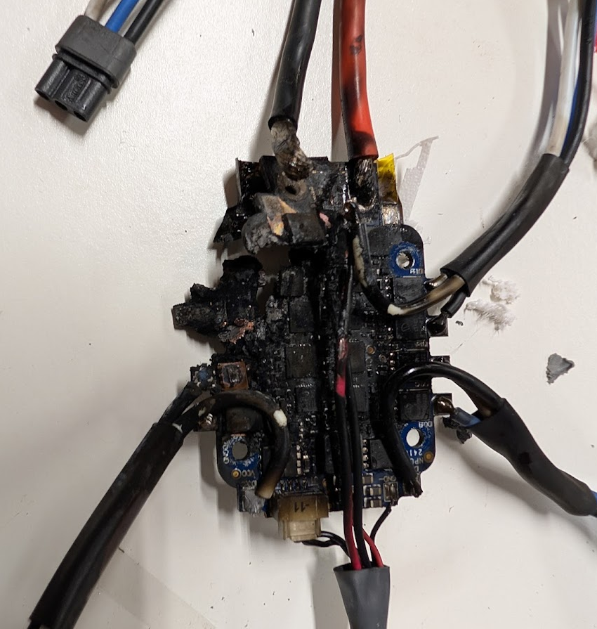
Thank you for the update. I am glad to see that your new tests went fine. As I mentioned before, i was quite surprised to see the ESC fail in such a way, which may suggest some kind of anomaly.
I will provide a longer answer soon, but for now some quick notes:
non-zero kp / ki parameters will speed up the ESC's RPM response. I will provide some examples
you can test whether the ESC closed-loop controller is stable using voxl-esc tools, using step inputs, etc. if unstable, lower Kp. Then lower Ki to avoid slow overshoots. Ki will definitely not contribute to high frequency oscillations.
assuming the ESC closed loop response is stable, if the Flight Controller is commanding noisy RPMs, the ESC with aggressive tuning (high kp) will try to track the noisy rpm commands, resulting in motor and ESC heating up.
there are generally two main sources of oscillations: unstable attitude controller or vibrations / noisy gyro
unstable attitude controller : characterized by lower frequency oscillations (in the range of 10-30Hz, depending on your frame, motors, etc)
vibrations can result from drone frame twisting at the frequency of motor RPM, or loose flight controller board / IMU, if flight board is shock mounted, the connected wires can potentially carry vibrations or cause the board to flex due to the wires vibrating / moving (very quickly). These vibrations will be at the frequency of motor RPM. aggressive (high) values of ESC kp will amplify these vibrations, so you can end up in a situation when the ESC's closed loop RPM controller is feeding back and contributing to higher oscillations.
by analyzing the gyro logs (will need to enable high rate logging), using FFT you can determine if your frame is mechanically unstable / noisy or the attitude controller is unstable.
if you set kp and ki to 0, you still have the advantage of calibrated (and voltage-compensated) RPM control. However, the control will only have feed-forward term. So behavior will be close to response of a traditional ESC with added calibrated feed-forward rpm control with voltage compensation.
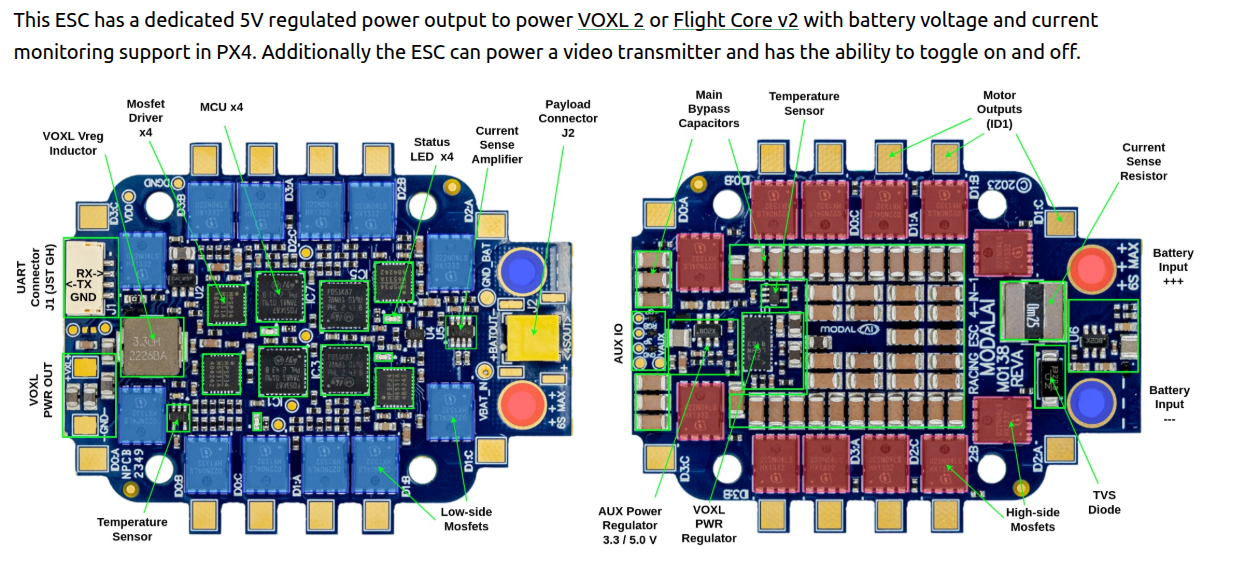
regarding whether you need a bigger ESC.. it depends on the maximum total current that you plan to pull. The M0138 ESC has been tested with similar motor / prop combo (3110 motor, 900kV with a 10x4.5 tri-blade) . During bench testing, each motor could pull close to 40A at 6S, however in practice you are never going to have all 4 motors spinning at absolute maximum rpm (then you will not have any control margin for attitude). We have tested full punch-out flights for 100+ Amps for over a minute and the ESC was perfectly fine (airflow required for cooling). The mosfets on M0138 are rated for 100A+ continuous (each), so 40A continuous an issue. It will come down to the total current draw and cooling. For high power applications like this, you should definitely start at lighter loads and try to push the ESC to the limit. You will also need to worry about power connector(s) if you are drawing 100A+ continuously (battery connector may melt).
px4 params: the min and max rpm params in px4 should match the min and max in your esc params. the px4 params do not override the limits in the esc params - the ESC will cap the incoming rpm commands if they are outside of the ESC params limits. Also, if you have incorrect px4 rpm limits, the thrust calculation in px4 will be incorrectly scaled from 0 to 100%, so you definitely want to get those rpm limits to be in sync between the ESC and px4.
Also, you can use our custom version of flight-review to display additional data specific to our ESC (rpm commands, actual rpms, esc temps, etc) : https://github.com/modalai/px4-flight-review (you can run it locally in docker).
Alex