@Pelle-Bredegg-Hermansen
Hi Pelle,
I emailed you the schematic review report for your considerations, just wanted to post here this task is completed.
Keep us posted!
Thanks!
@Pelle-Bredegg-Hermansen
Hi Pelle,
I emailed you the schematic review report for your considerations, just wanted to post here this task is completed.
Keep us posted!
Thanks!
Hi @Richa
We have not provided our pinouts for this and have no plans to.
For our Micro Coax direct CMOS based sensors, you need to use our products end-to-end to guarantee functionality.
Hope this helps clarify.
Hi @Pelle-Bredegg-Hermansen
I'll be happy to review your design.
I'll email you now to start the exchange.
Thanks!
Hi @cbay
Sorry, we do not share our PCB design data.
The best we did share is our Breakout Board Design noted here but that is SCH and an Altium Starter Kit w/o libs. Some symbols are in there you can try to export, but not many are in there.
https://docs.modalai.com/expansion-design-guide/#voxl-2-custom-expansion-pcb
And we have this design which we "kinda-sorta" opened a little bit for some schematic guidance.
https://docs.modalai.com/voxl2-dev-test-board/
Hope this helped.
Of note, if you do a board that is meant to mate with VOXL 2 J3/J5 or the camera group connectors J6-J8, I will review your schematic as a courtesy. Just reach out again and tag me, and I can email you privately so you are not posting your design on a public forum.
Hi @shawn_ricardo
Yes, any I2C port on an expansion board has 2.2K pullups to the voltage on Pin 1 of that connector.
The Linux Kernel user guide has info on which QUPS are enabled or not in which system image.

and specifically this helps:
https://docs.modalai.com/voxl2-qups/
Note not all QUPs have actually been enabled in the system, but with the sets of ports we have enabled, we never had any customer claim of a shortage:
Hi @Tormod-Axelsson-Hagen
Our descriptions tell you all you might need to know to make your own power module:
2-6S tolerant (so VIN capable of up to ~25.2V+)
6A output at 5V
Current monitoring if you do not use our ESCs (our ESCs provide a current reading to keep PX4 and other autopilots happy and for accurate remaining battery %)
Connector format of your choosing but the Molex 4-pin MINI SPOX is the direct 1:1 for VOXL 2 https://www.digikey.com/en/products/detail/molex/0022057045/403343?s=N4IgTCBcDaIAxzGOBWA7HALCkBdAvkA
The rest is up to you based on your design intent and supply chain constraints and preferred vendors.
Hope this helped!
@SDSU_Drones
Just to close this out, I emailed you a review report. Hope that helps you along your way.
Thanks!
Vinny
Hi @SDSU_Drones
You bet.... emailing you now!
Thanks!
Vinny
Hi @wetherbeej
We still never actively pursued support due to lack of demand.
Additionally, one of our other customers that is very savvy with QC chips tried for a few months and then gave up... seems this may be a fundamental QC QRB5165 issue that we may not be able to solve or even push for resolution either. It would not be the first SoC feature that was promised but then never supported. I think the lack of UFS cards in the market is a key indicator this product segment is going to eventually be left to dry.
Sorry I do not have better news for you.
As we push towards a later Ubuntu release, we can try again, but those efforts have been slow going and tedious.
Our other customer went towards a SSD over PCIe using J5 PCIe interface. That seems to be also where the market is heading... PCIe and USB-C based SSD's, but predominantly USB-C.
Hi @joseph-vale
This is not my wheel house, but maybe @Alex-Kushleyev can give you some pointers.
Thanks!
Vinny
@Ashish-Kumar
Few things:
After those steps are confirmed, then I think @tom can guide you further.
Thanks!
Hi @Aaky
You just went one page in too far 
https://docs.modalai.com/voxl-escs/
Hope this helps!
@Ashish-Kumar
With ONLY USB-C, the board will not boot, so that is normal behavior.
VBAT is always required.
D1 (Green LED) says the VBAT is present and our local 3.3V is ON.
With just that LED on, it tells me your board is likely stuck in QDL mode and needs reflashing, so the steps Tom provided will help confirm that.
Hi @dylangresham
Stinger is intended to be a complete drone package for developers, integrators, and system providers who do not require additional customization. We believe it includes all the necessary functionality for the FPV use case.
Starling 2, Starling 2 Max, and the PX4 Developer Editions, on the other hand, are designed to be customizable platforms that developers and integrators can modify to suit their specific products and use cases. By design, these are not fully Blue List–certified turnkey drones, since any additions, removals, or changes made by the end developer would require recertification.
That said, because most (if not all) of the subcomponents used in these platforms are already listed on the Blue UAS components list, the end-user certification process should be straightforward. ModalAI parts will pass screening easily thanks to their existing certifications.
I hope that clarifies the rationale.
Hi @snowt33nshi
All of our ucoax based image sensors use the same cables.
Be careful mating adapters to sensors as they are not all compatible as noted here:
https://docs.modalai.com/micro-coax-user-guide/
Hope this helps.
Hi @Jetson-Nano
Here is our info for Doodle Labs support:
https://docs.modalai.com/cable-datasheets/#mcbl-00085
Sorry it's buried in a cable page, but it makes the case clear (we think) how to support Doodle 

regarding probing USB signals, unless you had a USB decoder on the scope, I do not think that will prove anything useful. You may be better off running usbview:
Windows:
USBTreeView by Uwe Sieber — uwe-sieber.de/usbtreeview_e.html
It shows enumeration hierarchy, configuration descriptors, endpoints, VID/PID, power requirements, etc.
Linux equivalent:
Use usbview — it’s essentially the same utility (GTK front-end to lsusb).
Hope that helps!
Hi @will-huang-oksi
Are you willing to share some pics? Might be a cabling issue (GND loop or lack of a common GND), or some other intermittent connection causing your problems.
It really is hard to debug without seeing the setup.
Thanks!
Vinny
Hi @Nando75
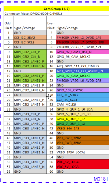
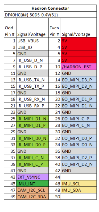
For the Boson portion of the Hadron, you need a 2L MIPI CSI config and for the EO portion you need a full 4-L MIPI CSI port, so you will be consuming an entire "Camera Group" from VOXL 2 for this.
You will want to assign the "lower" group to the Boson Portion in 2L mode and the full 4L "upper" group to the EO portion such that our SW matches up easily. Here are some mapping tables we constructed early on for this you can use as a guide (color based mapping, so hopefully that comes through OK).


However, please double check this and also let us know when you are ready for a SCH review. Tag me again on the Forum when you are ready, then I can email you at the address used for your Forum registration so you can share your SCH with me for a review.
Hope this helped!
Thanks!
Hi @Nando75
A shielded, impedance-controlled flex was our go-to solution in the early days, and we still offer a few legacy adapters that use it. These provide excellent signal integrity and EMI shielding. However, they’re limited in deployment flexibility; each flex must be meticulously designed for a specific routing path.
Coax, on the other hand, greatly improves routing versatility and can be deployed across many platforms. The trade-off is reduced signal distance and slightly degraded signal integrity compared to a tuned flex.
Ultimately, it’s a system-level tradeoff. We’ve transitioned to coax as our mainstream solution in recent years, driven by customer demand for easier installation without the constraints of custom flex circuits.
Only your team can decide what's more important and hopefully we can enable you either way.