Posts made by h3robotics
-
RE: mavlink peripherals
@Eric-Katzfey I would love to contribute!
I tried setting up voxl-cross. The pre-build version of voxl-cross is v2.7 on the downloads page. But I see that the voxl-cross in the repository has reached even v4. So I wanted to build voxl-cross myself. Unfortunately, the instructions say to download these files from the modalai downloads:
ubun1.0_1.8.04-M0054-14.1a-perf-20250421-rootfs.tar.tar
ubun2.0_2.0.0-perf-20250421-rootfs.tar.tarAnd I can't seem to find these files. Without that, I am unable to compile. Any suggestions on how to compile the latest voxl-cross? Or should I just use v2.7?
Thanks.
-
mavlink peripherals
Re: External MAVLink Connection using VOXL 2 through ttyHS1
Hi,
I am in need of integrating a mavlink gimbal and a parachute with the voxl2 autopilot. Mavlink is becoming a common protocol to communicate with a number of external peripherals like gimbal, parachute, engines etc. As such, there is a growing need to have voxl-mavlink-server be able to start a bi-directional mavlink stream on app UARTs like that on the USB3/UART Add on board (/dev/ttyHS1).
Is this something on the roadmap? Or any work arounds at the moment?
Thanks.
-
RE: EIS merge
@Alex-Kushleyev thank you so much. I can wait till the changes are merged and available to update directly on the voxl2.
Yes, I am using the IMX412 camera.
I can start off with whatever you have got for now and hope for a good video feed on my drone without any gimbal. As new changes come along, I will update.
I have never setup a build environment for voxl repos. I am used to building PX4 etc. with some of my custom changes. I would love to learn how to setup the build environment for the voxl repos. So if you can point me in the right direction, that would be great! I see in the docs, under "voxl SDK > custom voxl applications", there are some instructions.
Thank you!
-
RE: EIS merge
@Alex-Kushleyev said in EIS merge:
You will need to build the voxl-camera-server and voxl-portal packages from the appropriate branches. Hopefully you can do that by yourself. If not, i can post the test debs.
Hi @Alex-Kushleyev I want to use the EIS features. Would you be able to help me guide in the right direction of how to setup a build environment and build from the voxl-camera-server eis branch? Thank you.
-
RE: Unable to configure LTE modem
@Alex-Kushleyev That was it! I first tried with a lower baud rate of 250K on PX4 and I started getting the battery info. Then as you recommended, I uploaded new parameters to the ESC. I used:
python3 voxl-esc-upload-params.py --params-file ../voxl-esc-params/D0014_starling_1504_3000kv_ms_props/D0014_starling_1504_3000kv_ms_props.xml
because I will be using it on a drone of similar size and performance. Then with 2M baud rate in PX4, I was able to make it work!
Thank you.
-
RE: Unable to configure LTE modem
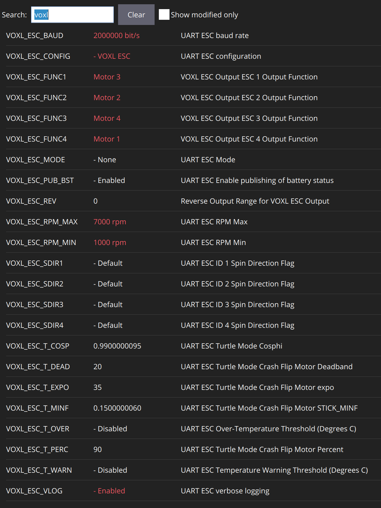
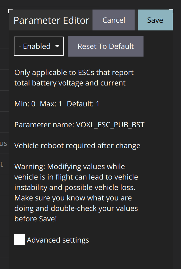
@Alex-Kushleyev No, it was default. I am using the latest QGround Control. Here are some images of the parameters.
All voxl related parameters:
VOXL_ESC_PUB_BST:
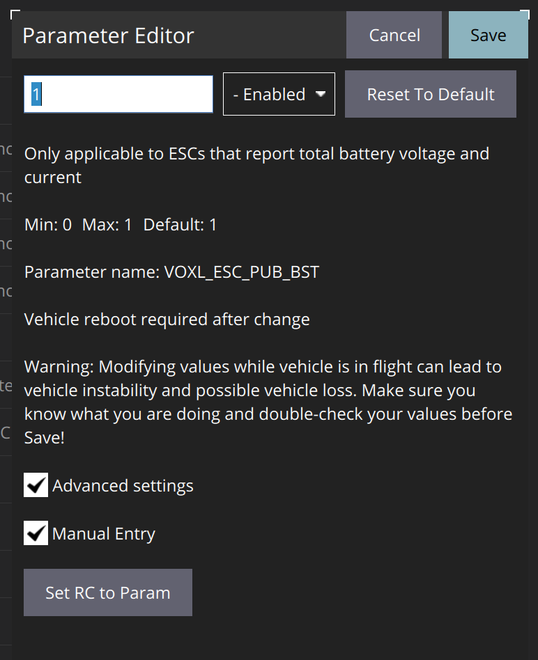
I also double checked using manual entry:
Let me know if that helps.
-
RE: Unable to configure LTE modem
@Eric-Katzfey VOXL_ESC_PUB_BST = Enabled and px4-listener battery_status gives "never published".
-
RE: Single camera config
@Alex-Kushleyev Thank you for your reply. I want to set up a single IMX412 camera (with same settings to start with) for live video streaming. I also want EIS and found a recent topic with your comments which I will follow.
For initial testing, I will be using the Starling 2 Adapter M0173 with one IMX412 camera. Once I purchase the single adapter (MDK-M0155-1), then I will use that instead.
I will try out what you proposed. Will reach out if there are any issues
Thank you.
Regards.
-
Single camera config
Hi all,
I currently have the Starling 2 Adapter M0173 with C29 config (dual IMX412, TOF, dual AR0144. I am able to configure the cameras using voxl-configure-cameras, and see all the four video feeds in the voxl portal.
I now want to create a custom configuration with Micro-coax Adapter (MDK-M0155-1) and single IMX412 camera. I see that I need to create a custom configuration file before running the voxl-configure-cameras command but I don't know how to do this pls.
Can someone help me to setup a single camera feed as mentioned above.
Thanks.
-
RE: Error in VOXL mini 4 in 1 ESC diagram
@Alex-Kushleyev the RX and TX lines need to be swapped at the J18 connector as well, please
-
RE: Unable to configure LTE modem
@Alex-Kushleyev it seems like after the wiring fix for the ESC, everything started to work properly.
- I measured the voltage b/w GND and pin 1 of J18 and it was around 3.3V.
- I also was able to configure the LTE modem without any issue.
- The ONLY problem I have now is that I don't see any battery voltage (or info) in voxl portal UI or QGround Control. I have the VOXL2 and Mini 4-in-1 ESC connected. I am under the impression that the ESC publishes battery info via the UART connection to the VOXL2 and the voxl-px4 service uses that to publish battery info? Am I correct? Am I missing something in the PX4 parameters or VOXL configuration?
Thank you for all your help!
-
RE: Unable to configure LTE modem
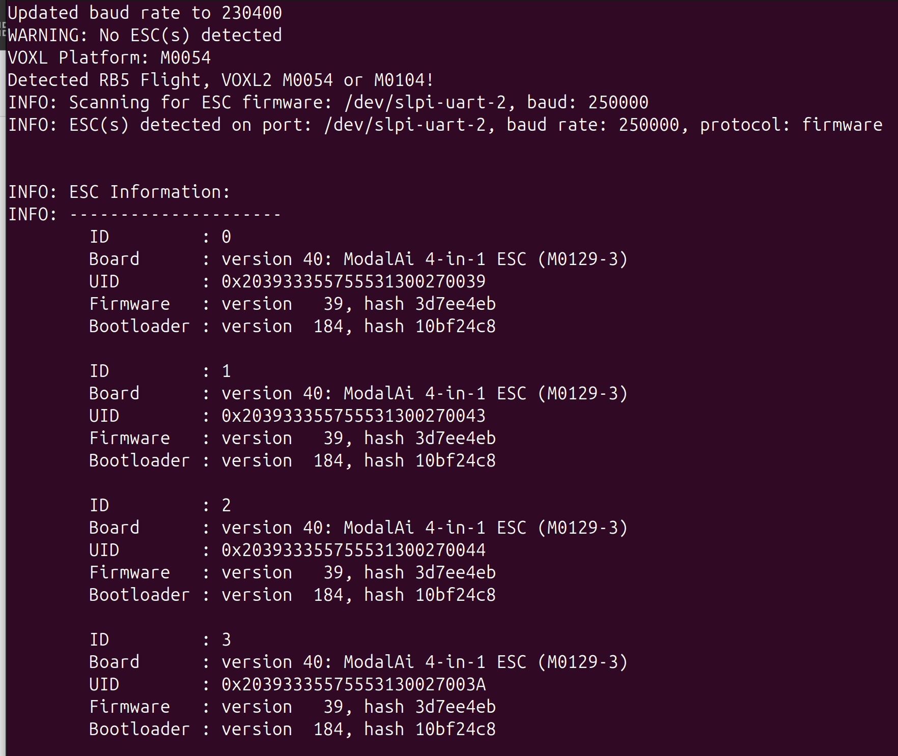
@Alex-Kushleyev I followed the steps. The ESC was detected in the scan:
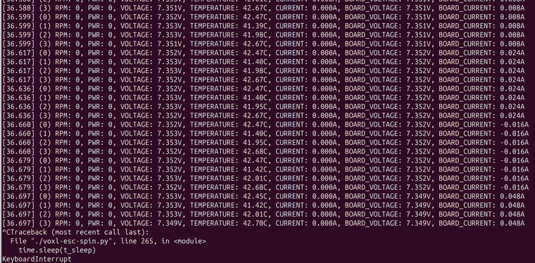
and the run command executed as:
My power supply is at 7.4V since I intend to power the drone with 2S pack. In idle, the power supply shows ~132mA and during the spin test the power supply showed 135mA - 148mA.
- Also the power output is 5V at the ESC when VOXL2 is connected.
-
RE: Unable to configure LTE modem
@Alex-Kushleyev here are the results:
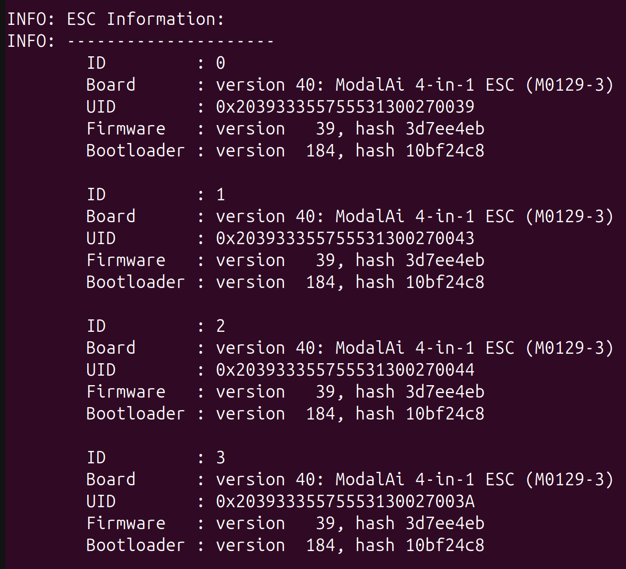
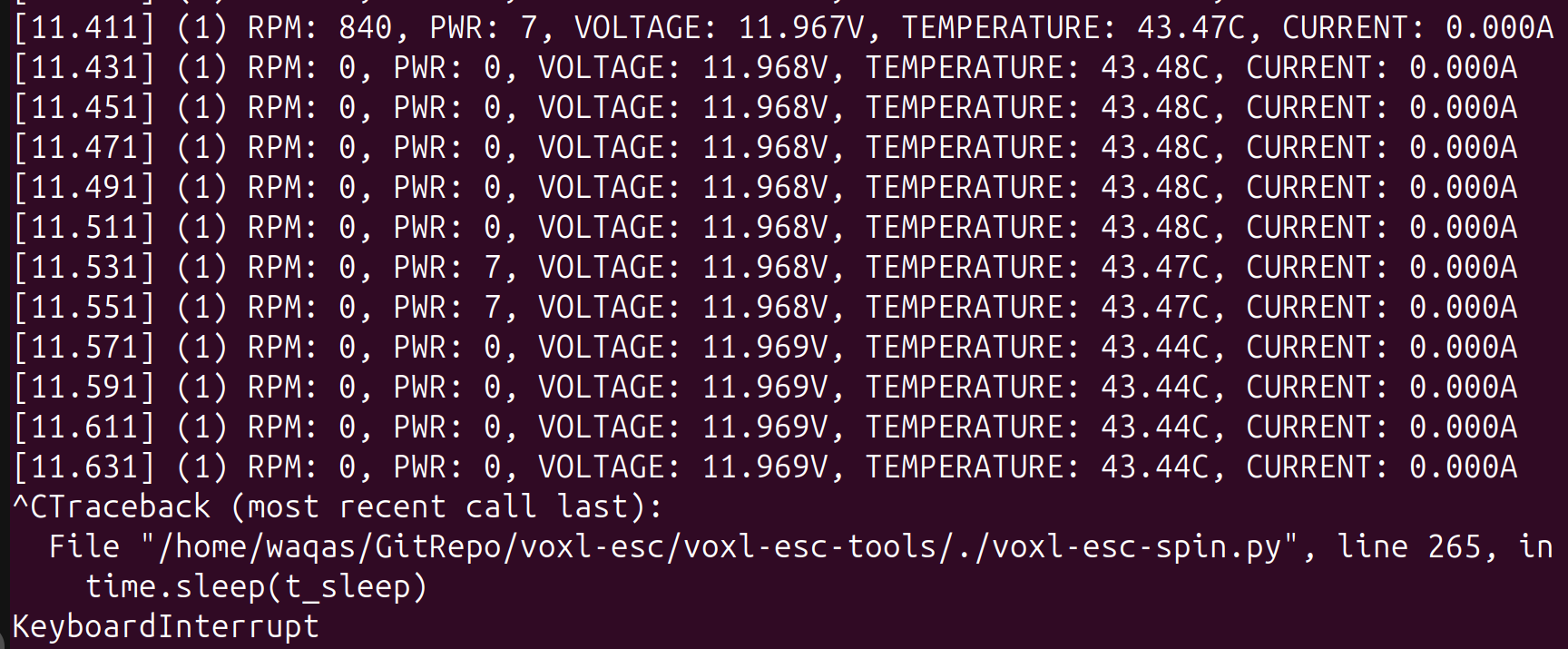
- I connected the ESC to a power supply (12V) and USB-UART(3.3v) cable. I was able to successfully scan and spin the ESC. See screenshots below:
I did not have any motors connected to the ESC but I did the spin test. I did see the current on my power supply jump from 38mA to ~55mA and all four LEDs were blinking blue.
-
When idle (ESC not spinning), the power supply was showing a current between 36mA - 38mA.
-
On bootup, the ESC blue LEDs rapidly flash for 1 s and then 2-3 blue blinks and then no blinking. When I spin the ESCs, the blue LEDs start blinking maybe once every second.
-
Using a voltmeter, I can see 5V on the power output.
Let me know the next steps
- I connected the ESC to a power supply (12V) and USB-UART(3.3v) cable. I was able to successfully scan and spin the ESC. See screenshots below:
-
RE: Unable to configure LTE modem
@Alex-Kushleyev just to confirm that I need to use a USB-to-UART (TTLv3.3) cable and connect it to the UART port J1 of the ESC?
Thank you for working through this with me. Really appreciate the support! -
RE: Unable to configure LTE modem
@tom can you look at this topic I just created. It turns out I was wiring the 4-in-1 ESC wrong as per a wiring diagram in the documentation.
https://forum.modalai.com/topic/4366/error-in-voxl-mini-4-in-1-esc-diagram
-
Error in VOXL mini 4 in 1 ESC diagram
Hi,
I am having strange issues with the VOXL2. I had hooked it up with a 4-in-1 mini ESC using the diagram here: https://docs.modalai.com/images/d0014/CWD-D0014-4-CXX-M22-TX-REV2.jpg. It turns out there is an error on the way wiring is shown (see the red circle):
With that wiring, I was unable to get the LTE v2 pro modem working. It was not being detected. I was also not able to get any battery info.
Now I have fixed the wiring as per the pinout of the connectors. But I am seeing the following issues:
- still I am not able to detect the LTE v2 modem.
- still no battery info. When I try to manually stop/start the "voxl_esc" driver in PX4 mavlink console, it gives me errors and fails to start.
- ADB over usb C does not work if the ESC UART connector J18 is not plugged into the VOXL 2.
Can you help me? I hope nothing is burnt/ broken due to the error in wiring above
-
RE: Unable to configure LTE modem
@Alex-Kushleyev I agree. When I put in the USB3/UART Add on board, I see that there is some clearance b/w the JST connector and the LTE board.
So it looks like the LTE modem is seated in properly. Looking forward to a solution to my problem of LTE setup -
RE: Unable to configure LTE modem
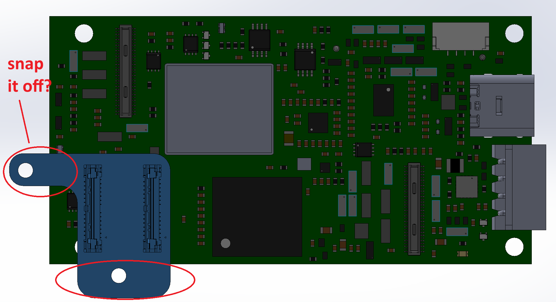
@tom when I was plugging in the modem, it did seem that the J1 connector does not go all the way in. But it is because of some small resistors that don't let the LTE modem seat completely.
I am attaching some pictures. Pic 1 and 2 shows the J1 connector side and the small resistor components.
Let me know if there is a solution to this