
PWM Servo IO Board
-
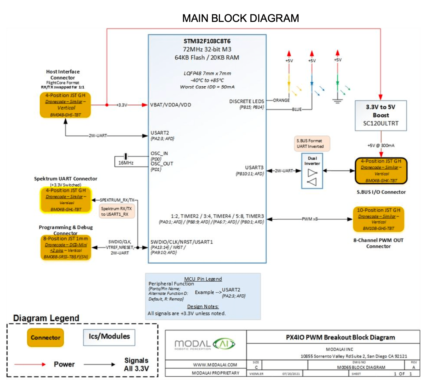
@valvarez The IO board was created to allow builders of custom drones who need to use PWM ESCs and / or SBUS RC units to be able to connect to a VOXL 2 which has neither PWM nor the ability to configure UARTs for SBUS. So, for example, if you wanted to use PWM ESCs instead of our UART based ESC then you would attach the IO board to the UART that normally is connected to the ESC. Or, for RC, you would connect (as in that diagram) to the UART that normally is connected to an RC receiver. If you still want to use our ESC, the current RC and GPS then you don't have a spare UART for the IO board. One possible way to do this would be to move the GPS from it's current connector to a UART on the applications processor side and then attach the IO board to the UART that has the GPS now. This would require an add-on board that exposes such a UART.
This post is deleted! -
@valvarez The IO board was created to allow builders of custom drones who need to use PWM ESCs and / or SBUS RC units to be able to connect to a VOXL 2 which has neither PWM nor the ability to configure UARTs for SBUS. So, for example, if you wanted to use PWM ESCs instead of our UART based ESC then you would attach the IO board to the UART that normally is connected to the ESC. Or, for RC, you would connect (as in that diagram) to the UART that normally is connected to an RC receiver. If you still want to use our ESC, the current RC and GPS then you don't have a spare UART for the IO board. One possible way to do this would be to move the GPS from it's current connector to a UART on the applications processor side and then attach the IO board to the UART that has the GPS now. This would require an add-on board that exposes such a UART.
@Eric-Katzfey said in PWM Servo IO Board:
@valvarez The IO board was created to allow builders of custom drones who need to use PWM ESCs and / or SBUS RC units to be able to connect to a VOXL 2 which has neither PWM nor the ability to configure UARTs for SBUS. So, for example, if you wanted to use PWM ESCs instead of our UART based ESC then you would attach the IO board to the UART that normally is connected to the ESC. Or, for RC, you would connect (as in that diagram) to the UART that normally is connected to an RC receiver. If you still want to use our ESC, the current RC and GPS then you don't have a spare UART for the IO board. One possible way to do this would be to move the GPS from it's current connector to a UART on the applications processor side and then attach the IO board to the UART that has the GPS now. This would require an add-on board that exposes such a UART.
Understood. And could you give me the reference of the add-on board to expose that UART?
-
@Eric-Katzfey said in PWM Servo IO Board:
@valvarez The IO board was created to allow builders of custom drones who need to use PWM ESCs and / or SBUS RC units to be able to connect to a VOXL 2 which has neither PWM nor the ability to configure UARTs for SBUS. So, for example, if you wanted to use PWM ESCs instead of our UART based ESC then you would attach the IO board to the UART that normally is connected to the ESC. Or, for RC, you would connect (as in that diagram) to the UART that normally is connected to an RC receiver. If you still want to use our ESC, the current RC and GPS then you don't have a spare UART for the IO board. One possible way to do this would be to move the GPS from it's current connector to a UART on the applications processor side and then attach the IO board to the UART that has the GPS now. This would require an add-on board that exposes such a UART.
Understood. And could you give me the reference of the add-on board to expose that UART?
-
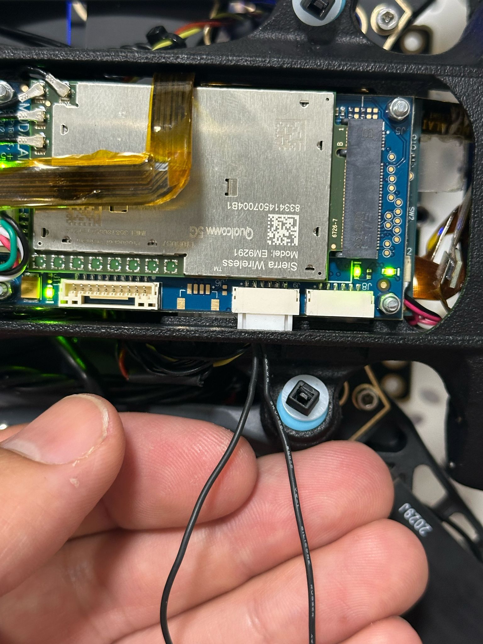
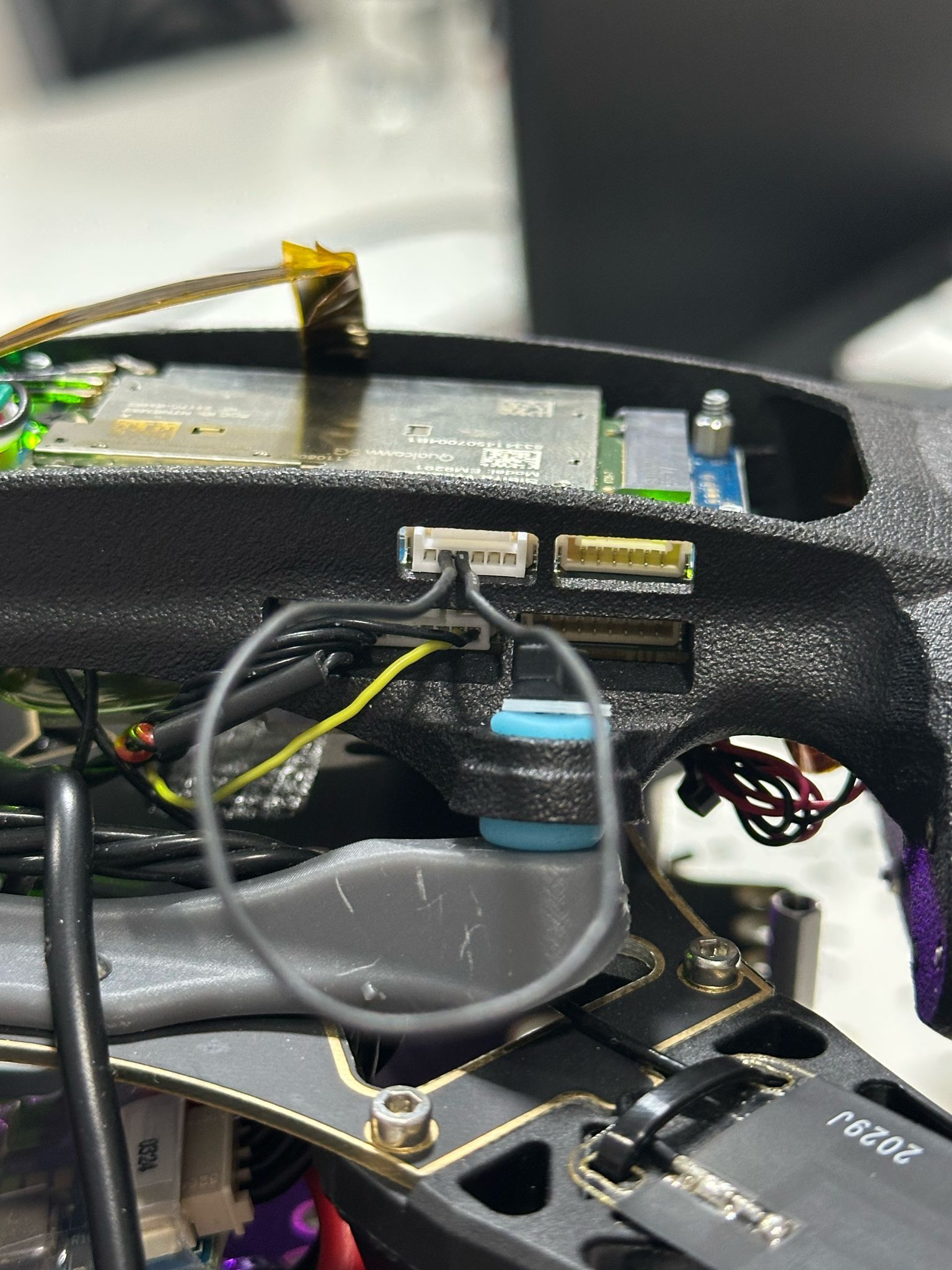
@Eric-Katzfey I already understood what you mean. What if that connector to which we connect the board that exposes the UART is occupied by the Sierra 5G Modem?
https://www.modalai.com/products/mdk-m0090?variant=40594936463411
I see in the datasheet that the J9 connector is a UART/i2c. Could the GPS be connected here to free it from the VOXL 2?
I'm starting to see the light...
Thanks @Eric-Katzfey
-
@Eric-Katzfey I already understood what you mean. What if that connector to which we connect the board that exposes the UART is occupied by the Sierra 5G Modem?
https://www.modalai.com/products/mdk-m0090?variant=40594936463411
I see in the datasheet that the J9 connector is a UART/i2c. Could the GPS be connected here to free it from the VOXL 2?
I'm starting to see the light...
Thanks @Eric-KatzfeyA bit hidden but it's /dev/ttyHS2
https://docs.modalai.com/voxl2-linux-user-guide/#devttyhs2---hsb2b-connector-uart
We ship a little helper tool that you can do a loop back test real quick if you make a cable that shorts pins 2/3:
qrb5165io-uart-test -d /dev/ttyHS2 -
A bit hidden but it's /dev/ttyHS2
https://docs.modalai.com/voxl2-linux-user-guide/#devttyhs2---hsb2b-connector-uart
We ship a little helper tool that you can do a loop back test real quick if you make a cable that shorts pins 2/3:
qrb5165io-uart-test -d /dev/ttyHS2@modaltb I don't think what you're telling me is useful to me, or I haven't understood you correctly.
That connector that you tell me is occupied by the M0090 -5g Add-on board, since it is a Sentinel with 5G.
My question is if there is a connector in that add-on to put the GPS and thus free up the VOXL connector where the IO Board will be connected. -
@modaltb I don't think what you're telling me is useful to me, or I haven't understood you correctly.
That connector that you tell me is occupied by the M0090 -5g Add-on board, since it is a Sentinel with 5G.
My question is if there is a connector in that add-on to put the GPS and thus free up the VOXL connector where the IO Board will be connected. -
@valvarez In the link that Travis shared you can see that the UART is exposed on J9 of the M0090 add-on board: "M0090 - 5G Add-On Board J9 Pins 2/3 (Tx/Rx)"
-
A bit hidden but it's /dev/ttyHS2
https://docs.modalai.com/voxl2-linux-user-guide/#devttyhs2---hsb2b-connector-uart
We ship a little helper tool that you can do a loop back test real quick if you make a cable that shorts pins 2/3:
qrb5165io-uart-test -d /dev/ttyHS2@modaltb
Hello.
I have tried this command following what you mentioned and it doesn't work.
Is there anything special I have to try?
Is it possible to connect the IO Board to the UART /dev/ttyHS2 taking this into account in the firmware update bash script?

-
@modaltb
Hello.
I have tried this command following what you mentioned and it doesn't work.
Is there anything special I have to try?
Is it possible to connect the IO Board to the UART /dev/ttyHS2 taking this into account in the firmware update bash script?
@valvarez , the usage for the test tool is as follows:
voxl2:/$ qrb5165io-uart-test -h
Description: runs hardware loopback test on specified bus

Usage: qrb5165io-uart-test

    -d <device ID> (eg 3 for /dev/ttyHS3)
So you should run your test as:
voxl2:/$ qrb5165io-uart-test -d 2
[INFO]: success!



Reading along? Create a free ModalAI Forum account to join in.
With an account you can reply, ask your own question, get an email when a ModalAI engineer answers, and mark the reply that solved it. Your place in each thread is saved between visits.
Questions about VOXL, Flight Core, ESCs and ModalAI drones are answered here by the engineers who build them.
Register Login