PWM Servo IO Board
-
@valvarez said in PWM Servo IO Board:
@valvarez that is correct you should power your servo from another power source capable if giving off 5V - if the servo has an operational range though of 3.3-5 then you can power it from the IO board.
Thanks
Zach -
@valvarez said in PWM Servo IO Board:
@valvarez that is correct you should power your servo from another power source capable if giving off 5V - if the servo has an operational range though of 3.3-5 then you can power it from the IO board.
Thanks
ZachHi @Zachary-Lowell-0 , @valvarez
ModalAI has no design capable of powering servos directly.
Every servo requires independent power.Thanks!
-
Hi @Zachary-Lowell-0 , @valvarez
ModalAI has no design capable of powering servos directly.
Every servo requires independent power.Thanks!
@Vinny Thanks @Zachary-Lowell-0 @Vinny !!
-
@Vinny Thanks @Zachary-Lowell-0 @Vinny !!
@valvarez Hello everyone!
I have received the IO Board, but I can't find a way to connect it to the Sentinel. I understand that you have to follow the connections in this image, but I'm not sure.
Could you give me some light?
Thank you!
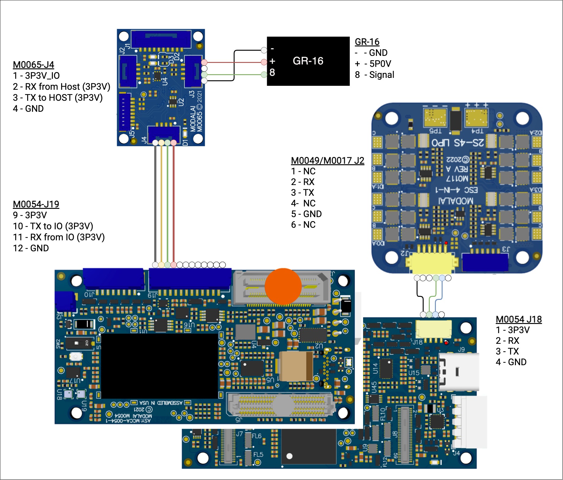
I understand that the connection indicated goes on those 4 pins, but this sensor is already connected.
-
@valvarez Hello everyone!
I have received the IO Board, but I can't find a way to connect it to the Sentinel. I understand that you have to follow the connections in this image, but I'm not sure.
Could you give me some light?
Thank you!
I understand that the connection indicated goes on those 4 pins, but this sensor is already connected.
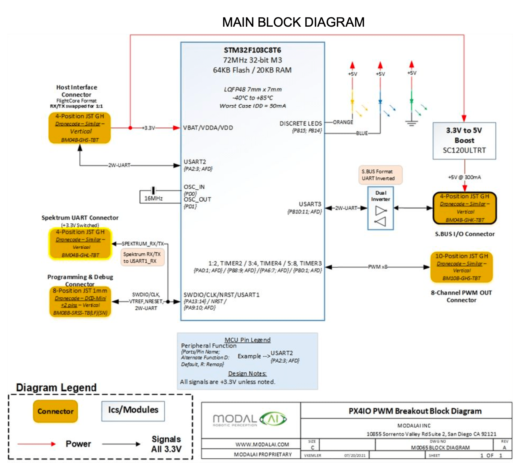
@valvarez The IO board was created to allow builders of custom drones who need to use PWM ESCs and / or SBUS RC units to be able to connect to a VOXL 2 which has neither PWM nor the ability to configure UARTs for SBUS. So, for example, if you wanted to use PWM ESCs instead of our UART based ESC then you would attach the IO board to the UART that normally is connected to the ESC. Or, for RC, you would connect (as in that diagram) to the UART that normally is connected to an RC receiver. If you still want to use our ESC, the current RC and GPS then you don't have a spare UART for the IO board. One possible way to do this would be to move the GPS from it's current connector to a UART on the applications processor side and then attach the IO board to the UART that has the GPS now. This would require an add-on board that exposes such a UART.
-
@valvarez The IO board was created to allow builders of custom drones who need to use PWM ESCs and / or SBUS RC units to be able to connect to a VOXL 2 which has neither PWM nor the ability to configure UARTs for SBUS. So, for example, if you wanted to use PWM ESCs instead of our UART based ESC then you would attach the IO board to the UART that normally is connected to the ESC. Or, for RC, you would connect (as in that diagram) to the UART that normally is connected to an RC receiver. If you still want to use our ESC, the current RC and GPS then you don't have a spare UART for the IO board. One possible way to do this would be to move the GPS from it's current connector to a UART on the applications processor side and then attach the IO board to the UART that has the GPS now. This would require an add-on board that exposes such a UART.
@Eric-Katzfey Thank you very much for the response. The kit I have purchased is the most complete one here: https://www.modalai.com/products/voxl2-io?variant=40905411035187
Would what you mention be possible with this hardware? -
@Eric-Katzfey Thank you very much for the response. The kit I have purchased is the most complete one here: https://www.modalai.com/products/voxl2-io?variant=40905411035187
Would what you mention be possible with this hardware?@valvarez That is the IO board. Yes, that's part of what I was talking about. Perhaps I don't quite understand your question. I would suggest creating a wiring diagram of your proposed system and including that in this thread. We can take a look and see if looks feasible. What you are proposing is a customization to the platform that we have never attempted so the best we can do is to take a look at your proposed design and provide some feedback on it.
-
@valvarez That is the IO board. Yes, that's part of what I was talking about. Perhaps I don't quite understand your question. I would suggest creating a wiring diagram of your proposed system and including that in this thread. We can take a look and see if looks feasible. What you are proposing is a customization to the platform that we have never attempted so the best we can do is to take a look at your proposed design and provide some feedback on it.
@Eric-Katzfey First of all, thank you for your patience.
My intention is to be able to connect a servo that allows a load to be released during the flight based on a signal sent by the VOXL itself (we will be connected to the drone through MAVLINK)
Seeing that there was no possibility of connecting a servo to the VOXL, I purchased the IO Board, to which I would connect the servo.
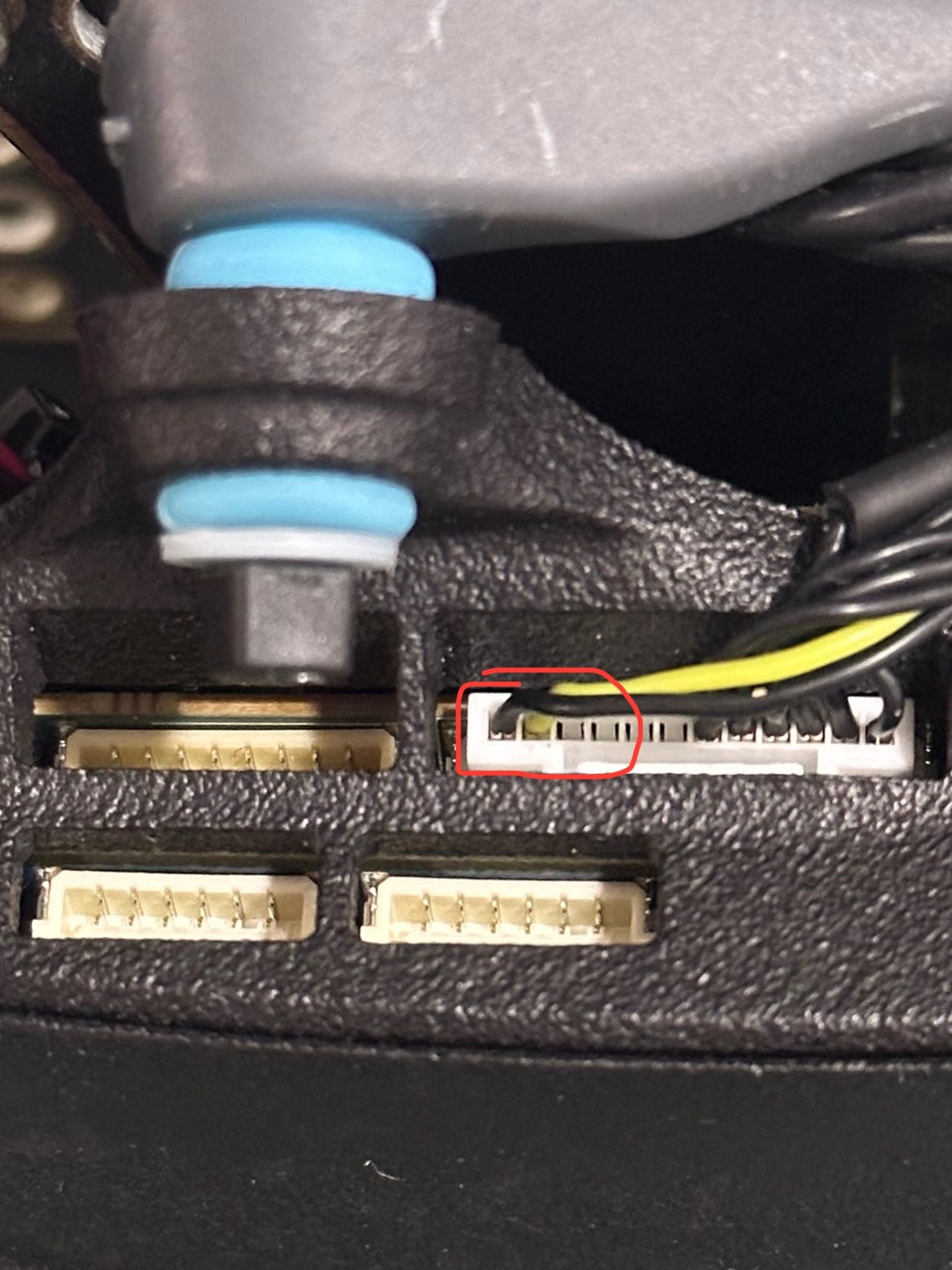
The thing is that when I see the connection diagram of the IO Board, I see that it is connected to a connector already used in the VOXL.
Is there any option that the device that is connected to the IO Board location can be connected to the IO Board, maintaining the option of using the RC that is supplied with the Sentinel and having the extra of being able to connect a deployment servo?Or failing that, if I wanted to send a signal through Mavlink to be able to release a load through a servo, what would the operation be like?
Thank you so much
-
@valvarez That is the IO board. Yes, that's part of what I was talking about. Perhaps I don't quite understand your question. I would suggest creating a wiring diagram of your proposed system and including that in this thread. We can take a look and see if looks feasible. What you are proposing is a customization to the platform that we have never attempted so the best we can do is to take a look at your proposed design and provide some feedback on it.
@Eric-Katzfey I think it has to do with this: https://forum.modalai.com/topic/1826/voxl-2-i-o-and-gps
Is it possible to connect the IO Board in parallel with the GPS connection? -
@Eric-Katzfey I think it has to do with this: https://forum.modalai.com/topic/1826/voxl-2-i-o-and-gps
Is it possible to connect the IO Board in parallel with the GPS connection?@valvarez No, you cannot connect two separate devices to the same UART.
-
@valvarez The IO board was created to allow builders of custom drones who need to use PWM ESCs and / or SBUS RC units to be able to connect to a VOXL 2 which has neither PWM nor the ability to configure UARTs for SBUS. So, for example, if you wanted to use PWM ESCs instead of our UART based ESC then you would attach the IO board to the UART that normally is connected to the ESC. Or, for RC, you would connect (as in that diagram) to the UART that normally is connected to an RC receiver. If you still want to use our ESC, the current RC and GPS then you don't have a spare UART for the IO board. One possible way to do this would be to move the GPS from it's current connector to a UART on the applications processor side and then attach the IO board to the UART that has the GPS now. This would require an add-on board that exposes such a UART.
This post is deleted! -
@valvarez The IO board was created to allow builders of custom drones who need to use PWM ESCs and / or SBUS RC units to be able to connect to a VOXL 2 which has neither PWM nor the ability to configure UARTs for SBUS. So, for example, if you wanted to use PWM ESCs instead of our UART based ESC then you would attach the IO board to the UART that normally is connected to the ESC. Or, for RC, you would connect (as in that diagram) to the UART that normally is connected to an RC receiver. If you still want to use our ESC, the current RC and GPS then you don't have a spare UART for the IO board. One possible way to do this would be to move the GPS from it's current connector to a UART on the applications processor side and then attach the IO board to the UART that has the GPS now. This would require an add-on board that exposes such a UART.
@Eric-Katzfey said in PWM Servo IO Board:
@valvarez The IO board was created to allow builders of custom drones who need to use PWM ESCs and / or SBUS RC units to be able to connect to a VOXL 2 which has neither PWM nor the ability to configure UARTs for SBUS. So, for example, if you wanted to use PWM ESCs instead of our UART based ESC then you would attach the IO board to the UART that normally is connected to the ESC. Or, for RC, you would connect (as in that diagram) to the UART that normally is connected to an RC receiver. If you still want to use our ESC, the current RC and GPS then you don't have a spare UART for the IO board. One possible way to do this would be to move the GPS from it's current connector to a UART on the applications processor side and then attach the IO board to the UART that has the GPS now. This would require an add-on board that exposes such a UART.
Understood. And could you give me the reference of the add-on board to expose that UART?
-
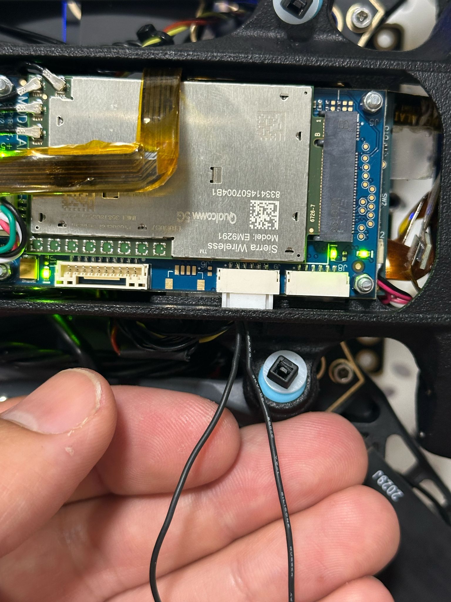
@Eric-Katzfey I already understood what you mean. What if that connector to which we connect the board that exposes the UART is occupied by the Sierra 5G Modem?
https://www.modalai.com/products/mdk-m0090?variant=40594936463411
I see in the datasheet that the J9 connector is a UART/i2c. Could the GPS be connected here to free it from the VOXL 2?
I'm starting to see the light...
Thanks @Eric-Katzfey
-
@Eric-Katzfey I already understood what you mean. What if that connector to which we connect the board that exposes the UART is occupied by the Sierra 5G Modem?
https://www.modalai.com/products/mdk-m0090?variant=40594936463411
I see in the datasheet that the J9 connector is a UART/i2c. Could the GPS be connected here to free it from the VOXL 2?
I'm starting to see the light...
Thanks @Eric-KatzfeyA bit hidden but it's /dev/ttyHS2

VOXL 2 Linux User Guide
ModalAI technical documentation for VOXL and VOXL 2 Companion Computers for PX4 and ArduPilot Obstacle Avoidance and GPS-denied navigation, assembled in the USA
ModalAI Technical Docs (docs.modalai.com)
We ship a little helper tool that you can do a loop back test real quick if you make a cable that shorts pins 2/3:
qrb5165io-uart-test -d /dev/ttyHS2 -
A bit hidden but it's /dev/ttyHS2
VOXL 2 Linux User Guide
ModalAI technical documentation for VOXL and VOXL 2 Companion Computers for PX4 and ArduPilot Obstacle Avoidance and GPS-denied navigation, assembled in the USA
ModalAI Technical Docs (docs.modalai.com)
We ship a little helper tool that you can do a loop back test real quick if you make a cable that shorts pins 2/3:
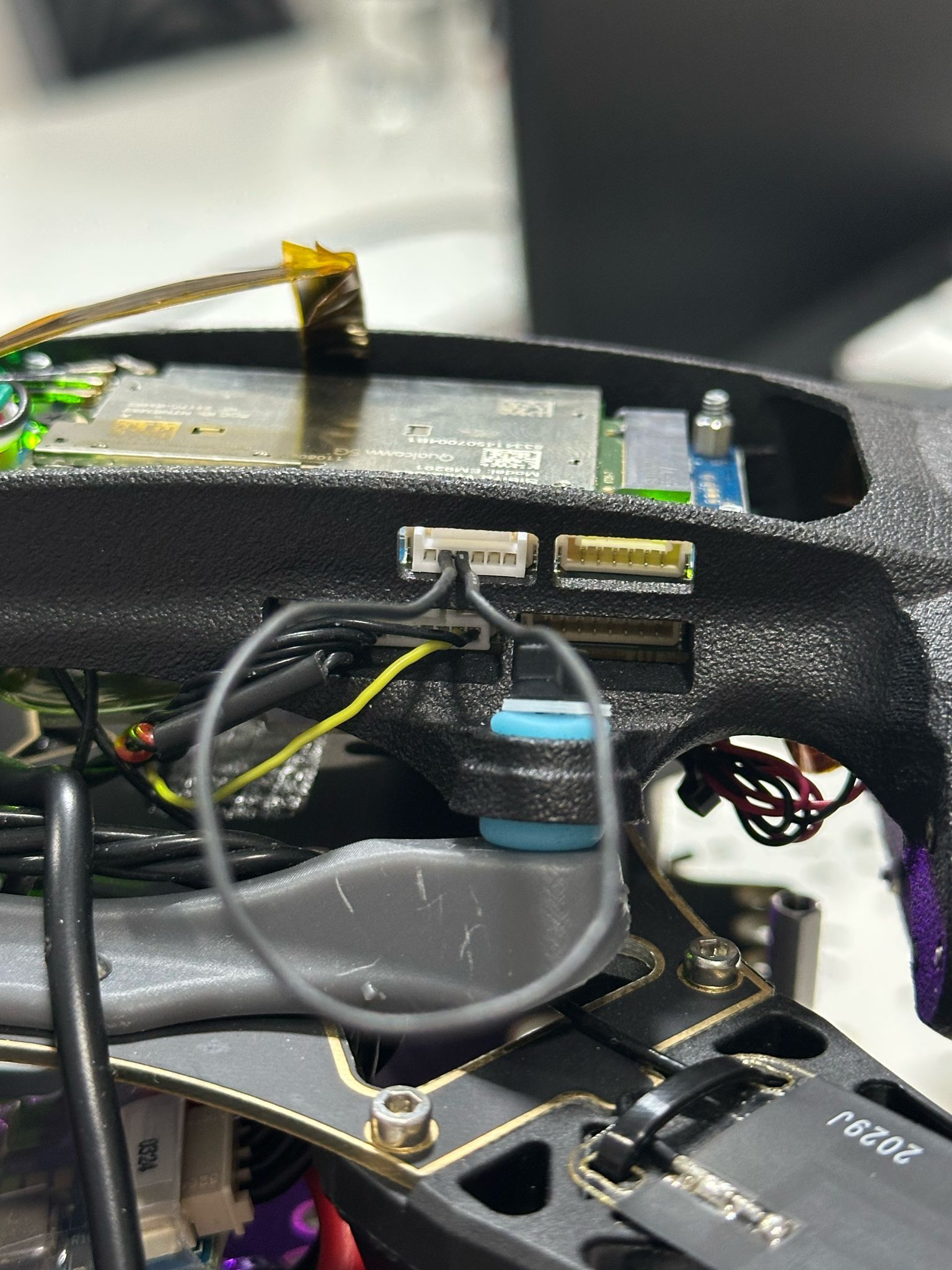
qrb5165io-uart-test -d /dev/ttyHS2@modaltb I don't think what you're telling me is useful to me, or I haven't understood you correctly.
That connector that you tell me is occupied by the M0090 -5g Add-on board, since it is a Sentinel with 5G.
My question is if there is a connector in that add-on to put the GPS and thus free up the VOXL connector where the IO Board will be connected. -
@modaltb I don't think what you're telling me is useful to me, or I haven't understood you correctly.
That connector that you tell me is occupied by the M0090 -5g Add-on board, since it is a Sentinel with 5G.
My question is if there is a connector in that add-on to put the GPS and thus free up the VOXL connector where the IO Board will be connected. -
@valvarez In the link that Travis shared you can see that the UART is exposed on J9 of the M0090 add-on board: "M0090 - 5G Add-On Board J9 Pins 2/3 (Tx/Rx)"
-
A bit hidden but it's /dev/ttyHS2
VOXL 2 Linux User Guide
ModalAI technical documentation for VOXL and VOXL 2 Companion Computers for PX4 and ArduPilot Obstacle Avoidance and GPS-denied navigation, assembled in the USA
ModalAI Technical Docs (docs.modalai.com)
We ship a little helper tool that you can do a loop back test real quick if you make a cable that shorts pins 2/3:
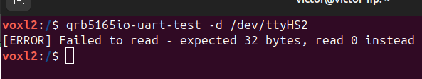
qrb5165io-uart-test -d /dev/ttyHS2@modaltb
Hello.
I have tried this command following what you mentioned and it doesn't work.
Is there anything special I have to try?
Is it possible to connect the IO Board to the UART /dev/ttyHS2 taking this into account in the firmware update bash script?
-
@modaltb
Hello.
I have tried this command following what you mentioned and it doesn't work.
Is there anything special I have to try?
Is it possible to connect the IO Board to the UART /dev/ttyHS2 taking this into account in the firmware update bash script?
@valvarez , the usage for the test tool is as follows:
voxl2:/$ qrb5165io-uart-test -h
Description: runs hardware loopback test on specified bus

Usage: qrb5165io-uart-test

    -d <device ID> (eg 3 for /dev/ttyHS3)
So you should run your test as:
voxl2:/$ qrb5165io-uart-test -d 2
[INFO]: success!
Hello! It looks like you're interested in this conversation, but you don't have an account yet.
Getting fed up of having to scroll through the same posts each visit? When you register for an account, you'll always come back to exactly where you were before, and choose to be notified of new replies (either via email, or push notification). You'll also be able to save bookmarks and upvote posts to show your appreciation to other community members.
With your input, this post could be even better 💗
Register Login