
Design review for a 4.5 kg VOXL 2 quad with M0138 on 12-inch props
-
Hi ModalAI team,
Hardware: Pre-build design review, so no serial numbers yet. Planned stack:
- VOXL 2 (MDK-M0154-1-00)
- VOXL 4-in-1 ESC (MDK-M0138-11-01, 5.1 V kit with VOXL 2 cables)
- M0130-3 LTE and USB hub add-on on J5
- M0048-2 Microhard USB carrier with pMDDL2450, on an M0130 USB port with its own 5 V supply
- M0226 front end with two M0166 AR0144 tracking cameras (front and down)
- M0184 ELRS receiver and M0224 GNSS on J19
- 4x Unusual Machines UM3115 900 kV motors, APC 12x6E props, 6S Li-ion pack
- About 4.5 kg take-off weight
Software version: Not built yet. We plan to start on SDK 1.8.
Configuration / services: Not built yet. Planned: voxl-px4 with the M0138 in closed-loop RPM mode capped at 9,100 rpm, VIO on the two tracking cameras, Microhard for C2, and a small service that drives J10 GPIO_46 as a 3.3 V camera trigger.
What I am trying to do: Confirm the ESC, power and I/O choices before we build the first airframe. A motor model gives about 19 A per motor at hover (about 6,350 rpm) and about 37 A at the 9,100 rpm cap. Could you help with these?
M0138:
- Is the 40 A rating phase current or bus current?
- What airflow does the 40 A continuous rating assume?
- The board senses total current only. How should each channel be protected at an rpm cap?
- You describe it for 5 to 10 inch airframes. Is a 12-inch prop acceptable, and what ESC tuning does it need?
VOXL 2 and accessories:
5. Is the M0224 supported as the PX4 navigation receiver on SDK 1.8?
6. On J10: what is the drive strength of GPIO_46 for a 3-way star at 3.3 V, which J10 mode does a shipped M0154 boot in, and what state are GPIO_46 and the J10 level shifter in from power-on until our trigger service takes the pin?
7. How much current may the M0130's J5 3.3 V pin supply? We need up to about 0.16 A.
8. Is about 3.3 A steady through VOXL 2 J4's single 5 V Mini-SPOX contact acceptable?
9. How long are the M0138 kit's VOXL 2 power and UART cables? Our runs are about 150 mm.
10. Is a STEP file available for the M0226?Handset:
11. What does the Zorro Blue (MRC-Z0001-1) cost on its own, and is it sold separately?
12. What are the form factor and price of the M0193 transmitter, and does it fit a standard controller module bay?What actually happens: Nothing yet. This is a design review before build.
Steps to reproduce: N/A
Logs / pictures: None yet. Happy to share a block diagram if useful.
-
Hi ModalAI team,
Hardware: Pre-build design review, so no serial numbers yet. Planned stack:
- VOXL 2 (MDK-M0154-1-00)
- VOXL 4-in-1 ESC (MDK-M0138-11-01, 5.1 V kit with VOXL 2 cables)
- M0130-3 LTE and USB hub add-on on J5
- M0048-2 Microhard USB carrier with pMDDL2450, on an M0130 USB port with its own 5 V supply
- M0226 front end with two M0166 AR0144 tracking cameras (front and down)
- M0184 ELRS receiver and M0224 GNSS on J19
- 4x Unusual Machines UM3115 900 kV motors, APC 12x6E props, 6S Li-ion pack
- About 4.5 kg take-off weight
Software version: Not built yet. We plan to start on SDK 1.8.
Configuration / services: Not built yet. Planned: voxl-px4 with the M0138 in closed-loop RPM mode capped at 9,100 rpm, VIO on the two tracking cameras, Microhard for C2, and a small service that drives J10 GPIO_46 as a 3.3 V camera trigger.
What I am trying to do: Confirm the ESC, power and I/O choices before we build the first airframe. A motor model gives about 19 A per motor at hover (about 6,350 rpm) and about 37 A at the 9,100 rpm cap. Could you help with these?
M0138:
- Is the 40 A rating phase current or bus current?
- What airflow does the 40 A continuous rating assume?
- The board senses total current only. How should each channel be protected at an rpm cap?
- You describe it for 5 to 10 inch airframes. Is a 12-inch prop acceptable, and what ESC tuning does it need?
VOXL 2 and accessories:
5. Is the M0224 supported as the PX4 navigation receiver on SDK 1.8?
6. On J10: what is the drive strength of GPIO_46 for a 3-way star at 3.3 V, which J10 mode does a shipped M0154 boot in, and what state are GPIO_46 and the J10 level shifter in from power-on until our trigger service takes the pin?
7. How much current may the M0130's J5 3.3 V pin supply? We need up to about 0.16 A.
8. Is about 3.3 A steady through VOXL 2 J4's single 5 V Mini-SPOX contact acceptable?
9. How long are the M0138 kit's VOXL 2 power and UART cables? Our runs are about 150 mm.
10. Is a STEP file available for the M0226?Handset:
11. What does the Zorro Blue (MRC-Z0001-1) cost on its own, and is it sold separately?
12. What are the form factor and price of the M0193 transmitter, and does it fit a standard controller module bay?What actually happens: Nothing yet. This is a design review before build.
Steps to reproduce: N/A
Logs / pictures: None yet. Happy to share a block diagram if useful.
Hello @jake_eizy ,
I will try to answer the ESC-related questions.
- The mosfets in M0138 ESC are rated for 100A+ continuous (each mosfet), so that is not going to be a limitation here.
- At hover, for your application, we are talking about almost 2kW of power flowing through the ESC board and even at 2% efficiency, the ESC would dissipate 40W. I don't have the exact efficiency numbers, but it should be somewhere in that ballpark.
- We have tested M0138 ESC with similar motors (3110 and 3115) with 10-inch props, drawing 80-85A during a very fast flight and the ESC temps were good (below 75C). The M0138 reports two temps from the MCU itself (the higher reading) and two board temps from separate temperature sensors.
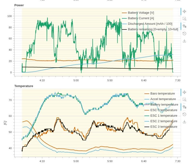
- in your case, the current draw will be 80A at hover, which means much less ambient air flow, compared to fast flight and your peak current draw will be almost double that.
- We have done short continuous tests for about 120A total (24V) and there were no issues, but the ESC required a significant amount of air cooling
- your application would push the M0138 ESC about 1.75x of what we have successfully tested in flight (in terms of total current through the ESC).
- my main concern would be thermal management and secondary concern is that additional bulk capacitance may be required via external capacitors (relatively easy to add to the ESC power pads). another thing to check is integrity of UART communication (packet loss) due to high transients (our tools allow to check that).
- The M0138 board does sense total current only, so no software current limiting (per ESC channel) is available. The
max_rpm_deltaterm in the RPM controller serves the purpose of limiting the current during transition, as it limits the maximum rpm that is used to to compute the error term in the controller. Max rpm delta translates to some max voltage delta (Vbatt * duty cycle) and that, in turn, translate into max current during the rpm transition. This is what we have right now in terms of software limits on current spikes. - the 12-inch propeller is just fine. the diameter does not matter, but the load on the motor does. You would need to do basic motor tuning, as described here (we can help with that as well) : https://gitlab.com/voxl-public/voxl-sdk/utilities/voxl-esc/-/blob/master/voxl-esc-tools/calibration.md
In summary, i would say that this would be a potentially doable but quite risky goal to achieve (80A continuous, 150A peak) . Would definitely need heat spreaders on both sides of the ESC board and a lot of airflow. the 4-in-1 ESC, being central to the vehicle, could be hard to get enough airflow, compared to single ESCs mounted on the arms, right under the propeller air flow (or in that area). Individual ESCs would not only have more thermal mass, board area, but also would have access to significant air flow. Also, any time you try to push the limits, you should start testing lower loads and build confidence that your set up is working properly and check everything along the way, including board temps, noise on commanded motor rpms (which can significantly add to the motor and ESC heating up). Unfortunately, we do not offer single ESCs, only 4-in-1.
I hope that answers your ESC questions. My colleague should follow up with other answers.
Alex
-
Thanks @alex-kushleyev , this is very helpful. One correction on my side: the 19 A and 37 A I quoted are per-motor phase currents from our motor model, not battery current. Our modeled battery current is about 38 A at hover (771 W at 20.4 V), about 35 A in survey flight, and about 95 A at the 9,100 rpm cap (about 107 A near 18 V), which we only expect in brief maneuvers. So the sustained load is about half of your 80 to 85 A flight test.
With those numbers:
-
Do you still see this as risky, and would you still fit heat spreaders on both sides? The ESC sits on the top plate near the center of the airframe, outside the prop wash.
-
What phase current per motor did your 80 to 85 A flight run at, so we can compare ESC heating?
-
Would you add external capacitance at this load, and what value would you start with?
-
Is there a starting value for max_rpm_delta you'd suggest for a 12-inch prop?
-
-
Hi @jake_eizy Answers below, in order.
- J10, GPIO_46
A shipped M0154 boots in SPI mode (GPIO_67 HIGH), exposed as /dev/spidev14.0. The mode is fixed in the kernel for a given build, not switchable at runtime. In that configuration GPIO_46 is on J10 pin 6 as an output. Pinouts for both modes: https://docs.modalai.com/voxl2-connectors/#j10---external-spi
Drive: the J10 signals are buffered to 3.3 V by an SN74LVC2T45, so ±24 mA, with VOH ≥ 2.4 V and VOL ≤ 0.55 V at that current.
For your 3-way star, 24 mA is not the limiting factor. Three CMOS receiver inputs are a negligible DC load. The constraint is AC. The 2T45’s native edge rate is fast enough that 150 mm branches are electrically long in FR4, and a star gives you three unterminated stubs that reflect into each other at the fanout point. Put a series damping resistor in each branch at the fanout.
- M0130 J5, 3.3 V at 0.16 A
Fine. J5 pin 1 is VREG_3P3V_LOCAL. Our cable-connector power outputs are rated 1 A each, though the system cannot supply 1 A on all connectors simultaneously: https://docs.modalai.com/voxl2-connectors/#power-inputoutput-important-note
0.16 A is well inside that. Budget it as part of your total 3.3 V draw rather than per-connector, since J5, J8 and J9 share the rail. Board mechanicals and the 3D STEP are in the PCB Catalog: https://docs.modalai.com/pcb-catalog/
- VOXL 2 J4, ~3.3 A steady on the 5 V contact
3.3 A sustained is not a concern. In practice our platforms already exceed the 3A pin spec rating: VOXL 2 requires 6 A of inrush support at power-on, so that contact sees well above 3.3 A as a transient on every boot of every system we ship. Sustained current is a different thermal problem from inrush, and what makes it workable is the thermal path rather than the contact alone.
- M0138 kit cable lengths
150 mm is not a problem, we stock multiple lengths. MCBL-00015-2 is the 150 mm variant: https://docs.modalai.com/cable-datasheets/#mcbl-00015
- M0226 STEP
We are adding M0226 and M0224 to the PCB Catalog now, including 3D STEP. Should be live shortly: https://docs.modalai.com/pcb-catalog/
-
Hi @jake_eizy, answers for 5 and part of 6.
5. M0224 on SDK 1.8
Not with the stock SDK 1.8 build. The M0224 uses an ST Teseo receiver, and voxl-px4 1.18.0-1.0.9 (the version in SDK 1.8) always starts the GPS driver with the u-blox protocol, so it will not see the M0224. voxl-px4 1.18.0-1.0.12 and newer probe for the M0224's BMM150 magnetometer and start the GPS driver with the Teseo protocol when it is found. That build is in the dev package repository now. There is also an M0224 parameter set in voxl-px4-params.
Details: https://docs.modalai.com/accessories/m0224/#px4-support
Startup logic: https://github.com/modalai/px4-firmware/blob/voxl-dev/boards/modalai/voxl2/target/voxl-px4-start6. J10 on M0154
A shipped M0154 boots with J10 in SPI mode. The stock kernel drives GPIO_67 (the J10 level shifter select) high and exposes /dev/spidev14.0 and /dev/spidev14.1. The mode is set in the kernel device tree, so UART mode needs a custom kernel build.
In SPI mode, GPIO_46 is the CS1 line (active low). On the SoC side, before the SN74LVC2T45 level shifter Vinny described, it is configured for 6 mA drive with no pull, and it is held high once the kernel SPI driver loads. The ±24 mA figure at the J10 pin comes from the level shifter.
Details: https://docs.modalai.com/voxl2-connectors/#j10---external-spi
-
Vinny and Tom, thank you so much!! Final Follow up questions below and I should be good
-
Can a userspace service drive GPIO_46 as a plain output while the kernel SPI driver holds it as CS1 for /dev/spidev14.1, or do we need to remove that chip select from the device tree?
-
What state are GPIO_46 and the level shifter in from power-on until the SPI driver loads?
-
On the ESC cables:
-
Does MCBL-00015-2 replace the kit's UART cable? It's listed as straight-through 1:1, but the M0138 data sheet says to leave J1 pin 1 (3.3 V reference out) unconnected, and our notes show VOXL 2 J18 pin 1 also carries 3.3 V. Is the 1:1 cable fine on the M0138, or should pin 1 be left open?
-
Can the 150 mm -2 version be ordered for a production build?
-
Is there a 150 mm version of the kit's VOXL 2 power cable?
- Is a stable SDK planned that includes voxl-px4 1.18.0-1.0.12 or newer?
-

Reading along? Create a free ModalAI Forum account to join in.
With an account you can reply, ask your own question, get an email when a ModalAI engineer answers, and mark the reply that solved it. Your place in each thread is saved between visits.
Questions about VOXL, Flight Core, ESCs and ModalAI drones are answered here by the engineers who build them.
Register Login