
Starling 2 Max no GPS data
-
@Alex-Kushleyev Have you made any progress with this yet? Please let me know if/how I can help.
@ROBERT-JUDD , thank you for your patience. A few updates.
Please note that this is an effort to come up with a short term workaround the issues with GNSS interference, so it may not be the most elegant solution.
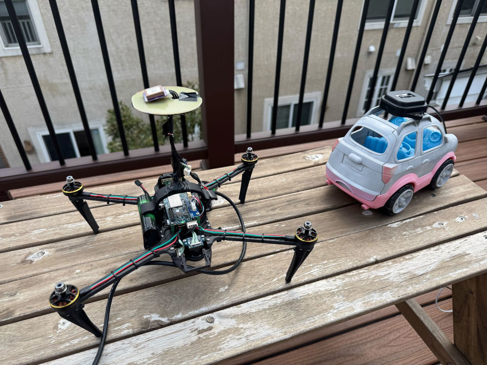
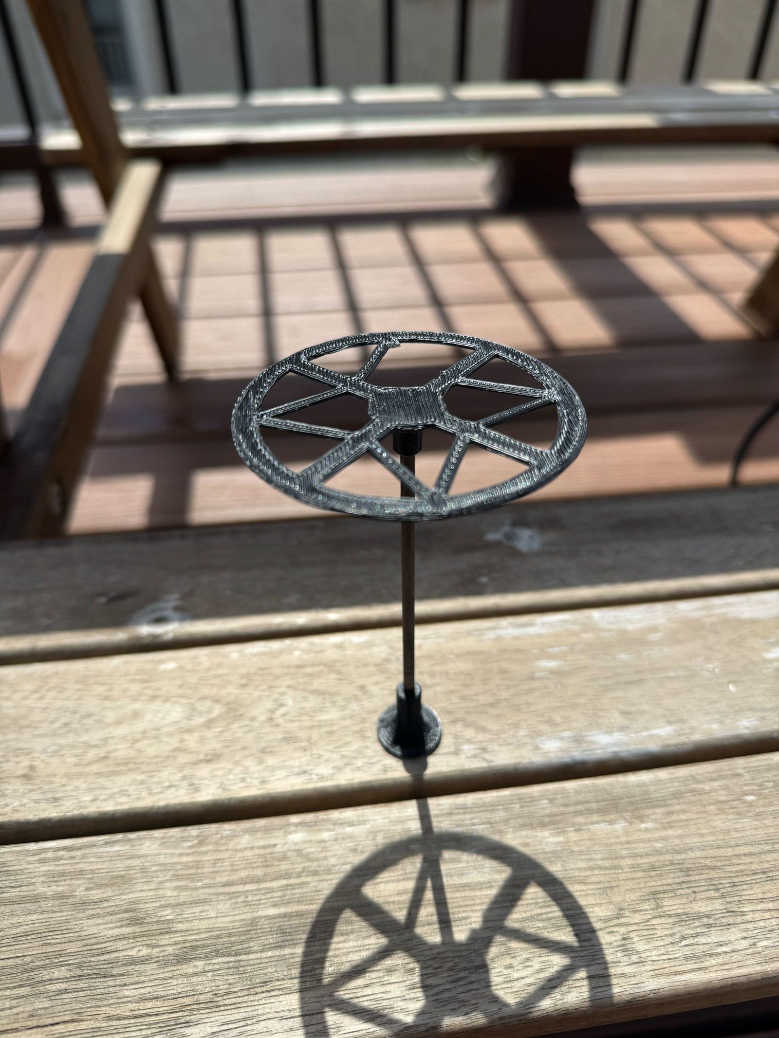
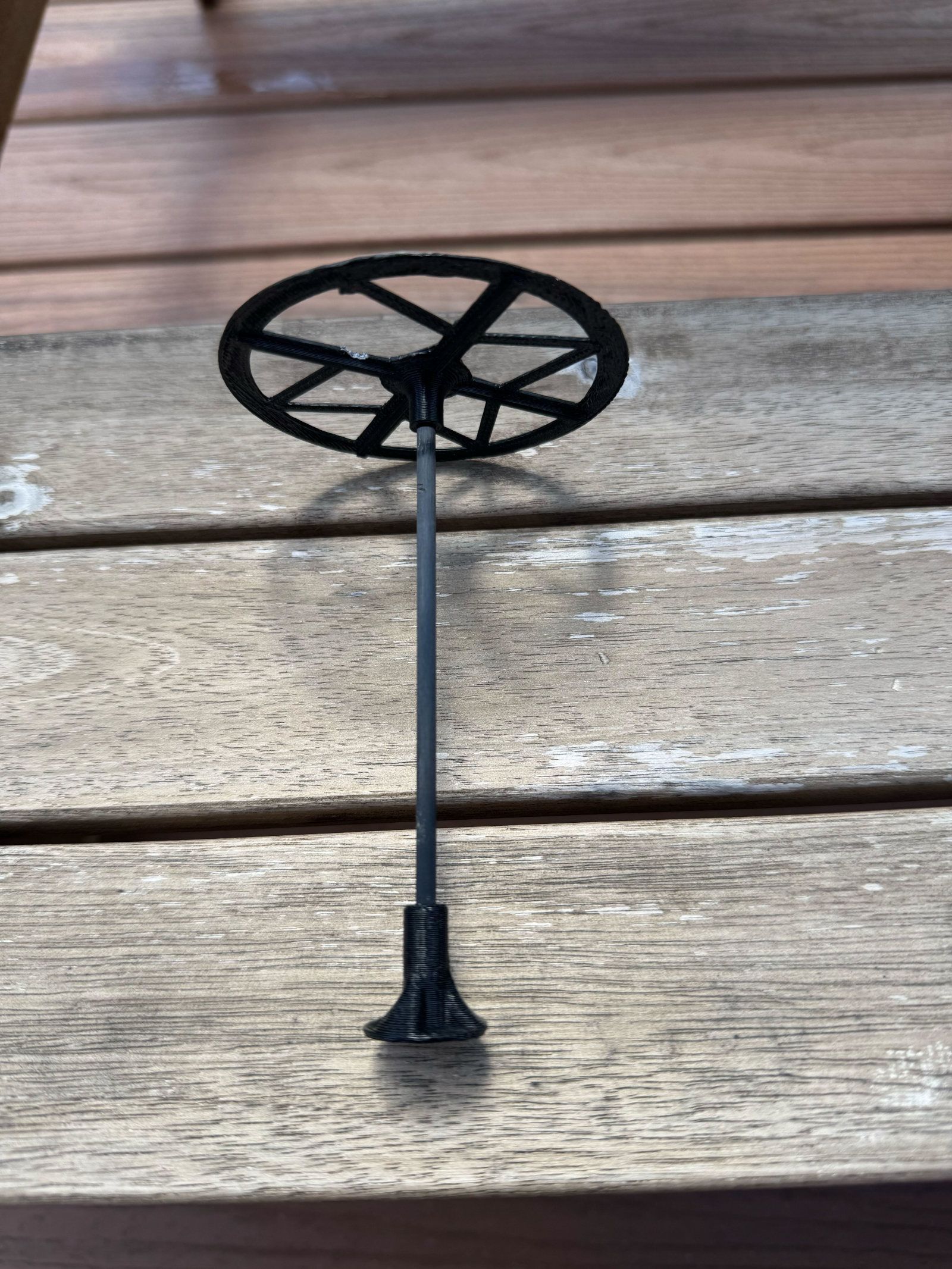
- I have used a mast to offset the GNSS receiver upwards in order to get it further from the interference source(s). The mast is about 4.25 inches (11cm) tall. It is made up of a carbon fiber rod and two 3d printed parts.
- Images of the mast attached
- on top of the 3d printed plastic, there is a FR4 disk with a copper layer (on the bottom of the FR4 board, so it is not shown in the image)
- the 6-wire cable was extended to reach to the top of the mast (the extension is not very clean, i will make a better cable soon and test again).
- the mast was attached on top of the roll cage, but also tested with the mast sitting on top of the location in the back, where the GNSS receiver was originally located (while elevated from that location by the mast)
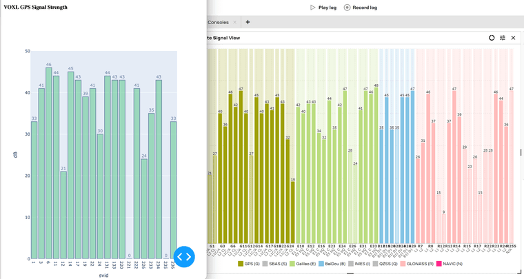
- in order to compare know what SNR to expect, i hooked up a Ublox EVK to my laptop so i can use Ucenter2 to plot the signal strengths while the EVK is placed about 2ft from the drone.
- we now have a simple python script that can grab the satellite info from px4 (satellite info needs to be enabled via px4 param, see script), so that the bar graph of voxl2 gps SNRs can be running live on a laptop that is also running ucenter.
Results
- using the mast with the FR4 (with copper) shield achieves SNRs that are very close to the SNRs from EVK
- Running Commando 8 transmitter in close proximity (less than 5ft, the closer the worse, especially TX antenna above the gps antenna) to the gps receiver can degrade SNR up to 10dB !! This can happen if you are standing right next to the drone before take off. It looks like the RC TX is saturating the GNSS receiver, even though the RC is in the 900mhz band.
- the shield on top of the mast (FR4+copper, but i also tried thin carbon fiber) helps increase SNR by around 3-6dB. Also, it may be good to add some copper tape (with non-conductive adhesive) to cover up the back of the GNSS receiver in order to prevent noise being injected into the short trace connecting the antenna and the GNSS receiver. I will try that, need to buy some copper tape. Using copper tape can reduce the mass of the top of the mast (the FR4 itself does nothing for shielding, since it's not conductive)
- I found better results when the 6-conductor cable is tightly wrapped around the mast as opposed to hanging loose , I may consider trying a shielded cable, perhaps there is some noise that can be picked up by the conductors as well (TBD)
- I would like to flight test this configuration (TBD, maybe Weds or Thurs). It is important to make sure the mast is stable and does not vibrate.
- the Lepton cable did not seem to matter, whether it was plugged in or not, i did not see any change when using the mast and unplugging the lepton cable in real-time.
- wifi dongle did not affect the gps signal, especially since it's normally mounted underneath the drone
Conclusion:
- based on these numbers from a non-moving test, the satellite signal strength looked very good (can't do much better than that) and I got a DGPS lock (i guess SBAS)
Other Thoughts
- using a GNSS receiver with a larger antenna, can help a bit more, but it will also increase the weight on top of the mast
You could try to replicate this type of testing and use a second (reference) gps receiver so you can compare the SNR to a (close to) ideal gps receiver without any interference. The reason for this is that the satellite SNR vary significantly as their position changes (over time), so a reference will allow you to always see what the SNR for each satellite (roughly) should be.
Images and plots:
SNR plot. Left: Starling 2 Max (plot using attached script), Right: Ublox EVK (using Ucenter2)
Mast
GPS SNR Plot script (run on voxl and then open the browser using <voxl-ip>:8050 . Install the dependencies (see script) and run using
python3 gps_satellite_info.pyimport subprocess import time import numpy as np import argparse import ast import plotly.graph_objects as go from dash import Dash, dcc, html, Input, Output # pip3 install plotly typing-extensions dash --upgrade parser = argparse.ArgumentParser(description='GPS Test Script') args = parser.parse_args() # to enable publishing of satellite info, set px4 param (and restart px4): # param set GPS_SAT_INFO 1 #px4-listener satellite_info # #TOPIC: satellite_info # satellite_info # timestamp: 2611309684 (0.868903 seconds ago) # count: 13 # svid: [5, 8, 10, 13, 15, 18, 23, 24, 27, 32, 131, 133, 138, 0, 0, 0, 0, 0, 0, 0] # used: [1, 1, 1, 0, 1, 0, 1, 1, 0, 1, 1, 1, 1, 0, 0, 0, 0, 0, 0, 0] # elevation: [11, 1, 30, 11, 47, 64, 68, 59, 13, 15, 27, 19, 33, 0, 0, 0, 0, 0, 0, 0] # azimuth: [74, 232, 213, 36, 37, 138, 241, 85, 209, 172, 165, 173, 158, 0, 0, 0, 0, 0, 0, 0] # snr: [0, 0, 26, 17, 32, 14, 29, 30, 15, 0, 0, 0, 0, 0, 0, 0, 0, 0, 0, 0] # prn: [5, 8, 10, 13, 15, 18, 23, 24, 27, 32, 131, 133, 138, 0, 0, 0, 0, 0, 0, 0] def get_px4_satellite_info(): cmd = 'px4-listener satellite_info' p = subprocess.Popen(cmd, shell=True, stdout=subprocess.PIPE, stderr=subprocess.STDOUT) timestamp = None count = 0 svid = None used = None elev = None azim = None snr = None prn = None for line in p.stdout.readlines(): l=str(line) #print(l) if 'timestamp' in l: ll = l.split(':')[1].split()[0] timestamp = float(ll) if 'count' in l: ll = l.split(':')[-1][:-3] count = int(ll) if 'svid' in l: ll = l.split(':')[-1][:-3] svid = np.array(ast.literal_eval(ll.strip())) if 'used' in l: ll = l.split(':')[-1][:-3] used = np.array(ast.literal_eval(ll.strip())) if 'snr' in l: ll = l.split(':')[-1][:-3] snr = np.array(ast.literal_eval(ll.strip())) if 'prn' in l: ll = l.split(':')[-1][:-3] prn = np.array(ast.literal_eval(ll.strip())) retval = p.wait() return (timestamp, count, svid, used, snr, prn) app = Dash(__name__) app.layout = html.Div([ html.H4('VOXL GPS Signal Strength '), html.Div(id='output'), dcc.Interval(id='interval-component', interval=1000, n_intervals=0), ]) @app.callback( Output("output", "children"), Input('interval-component', 'n_intervals')) def display_graph(render_option): (timestamp, count, svid, used, snr, prn) = get_px4_satellite_info() idx_valid = np.logical_and(svid != 0, svid != 255) svid_plot = svid[idx_valid] svids = [str(x) for x in svid_plot] snrs = snr[idx_valid] print('svid : ', svids) print('snr : ', snrs) fig = go.Figure() fig.add_trace(go.Bar(x=svids, y=snrs, text=snrs, textposition='outside')) fig.update_traces(marker_color='rgb(100,202,150)', marker_line_color='rgb(8,48,107)',marker_line_width=1.5, opacity=0.6) fig.update_layout( yaxis=dict(range=[0, 50], title=dict(text='dB') ) ) fig.update_layout( xaxis=dict(title=dict(text='svid') ) ) fig.update_layout(height=800) return dcc.Graph(figure=fig) app.run(debug=True, host='0.0.0.0') -
A Alex Kushleyev referenced this topic on
-
@ROBERT-JUDD , thank you for your patience. A few updates.
Please note that this is an effort to come up with a short term workaround the issues with GNSS interference, so it may not be the most elegant solution.
- I have used a mast to offset the GNSS receiver upwards in order to get it further from the interference source(s). The mast is about 4.25 inches (11cm) tall. It is made up of a carbon fiber rod and two 3d printed parts.
- Images of the mast attached
- on top of the 3d printed plastic, there is a FR4 disk with a copper layer (on the bottom of the FR4 board, so it is not shown in the image)
- the 6-wire cable was extended to reach to the top of the mast (the extension is not very clean, i will make a better cable soon and test again).
- the mast was attached on top of the roll cage, but also tested with the mast sitting on top of the location in the back, where the GNSS receiver was originally located (while elevated from that location by the mast)
- in order to compare know what SNR to expect, i hooked up a Ublox EVK to my laptop so i can use Ucenter2 to plot the signal strengths while the EVK is placed about 2ft from the drone.
- we now have a simple python script that can grab the satellite info from px4 (satellite info needs to be enabled via px4 param, see script), so that the bar graph of voxl2 gps SNRs can be running live on a laptop that is also running ucenter.
Results
- using the mast with the FR4 (with copper) shield achieves SNRs that are very close to the SNRs from EVK
- Running Commando 8 transmitter in close proximity (less than 5ft, the closer the worse, especially TX antenna above the gps antenna) to the gps receiver can degrade SNR up to 10dB !! This can happen if you are standing right next to the drone before take off. It looks like the RC TX is saturating the GNSS receiver, even though the RC is in the 900mhz band.
- the shield on top of the mast (FR4+copper, but i also tried thin carbon fiber) helps increase SNR by around 3-6dB. Also, it may be good to add some copper tape (with non-conductive adhesive) to cover up the back of the GNSS receiver in order to prevent noise being injected into the short trace connecting the antenna and the GNSS receiver. I will try that, need to buy some copper tape. Using copper tape can reduce the mass of the top of the mast (the FR4 itself does nothing for shielding, since it's not conductive)
- I found better results when the 6-conductor cable is tightly wrapped around the mast as opposed to hanging loose , I may consider trying a shielded cable, perhaps there is some noise that can be picked up by the conductors as well (TBD)
- I would like to flight test this configuration (TBD, maybe Weds or Thurs). It is important to make sure the mast is stable and does not vibrate.
- the Lepton cable did not seem to matter, whether it was plugged in or not, i did not see any change when using the mast and unplugging the lepton cable in real-time.
- wifi dongle did not affect the gps signal, especially since it's normally mounted underneath the drone
Conclusion:
- based on these numbers from a non-moving test, the satellite signal strength looked very good (can't do much better than that) and I got a DGPS lock (i guess SBAS)
Other Thoughts
- using a GNSS receiver with a larger antenna, can help a bit more, but it will also increase the weight on top of the mast
You could try to replicate this type of testing and use a second (reference) gps receiver so you can compare the SNR to a (close to) ideal gps receiver without any interference. The reason for this is that the satellite SNR vary significantly as their position changes (over time), so a reference will allow you to always see what the SNR for each satellite (roughly) should be.
Images and plots:
SNR plot. Left: Starling 2 Max (plot using attached script), Right: Ublox EVK (using Ucenter2)
Mast
GPS SNR Plot script (run on voxl and then open the browser using <voxl-ip>:8050 . Install the dependencies (see script) and run using
python3 gps_satellite_info.pyimport subprocess import time import numpy as np import argparse import ast import plotly.graph_objects as go from dash import Dash, dcc, html, Input, Output # pip3 install plotly typing-extensions dash --upgrade parser = argparse.ArgumentParser(description='GPS Test Script') args = parser.parse_args() # to enable publishing of satellite info, set px4 param (and restart px4): # param set GPS_SAT_INFO 1 #px4-listener satellite_info # #TOPIC: satellite_info # satellite_info # timestamp: 2611309684 (0.868903 seconds ago) # count: 13 # svid: [5, 8, 10, 13, 15, 18, 23, 24, 27, 32, 131, 133, 138, 0, 0, 0, 0, 0, 0, 0] # used: [1, 1, 1, 0, 1, 0, 1, 1, 0, 1, 1, 1, 1, 0, 0, 0, 0, 0, 0, 0] # elevation: [11, 1, 30, 11, 47, 64, 68, 59, 13, 15, 27, 19, 33, 0, 0, 0, 0, 0, 0, 0] # azimuth: [74, 232, 213, 36, 37, 138, 241, 85, 209, 172, 165, 173, 158, 0, 0, 0, 0, 0, 0, 0] # snr: [0, 0, 26, 17, 32, 14, 29, 30, 15, 0, 0, 0, 0, 0, 0, 0, 0, 0, 0, 0] # prn: [5, 8, 10, 13, 15, 18, 23, 24, 27, 32, 131, 133, 138, 0, 0, 0, 0, 0, 0, 0] def get_px4_satellite_info(): cmd = 'px4-listener satellite_info' p = subprocess.Popen(cmd, shell=True, stdout=subprocess.PIPE, stderr=subprocess.STDOUT) timestamp = None count = 0 svid = None used = None elev = None azim = None snr = None prn = None for line in p.stdout.readlines(): l=str(line) #print(l) if 'timestamp' in l: ll = l.split(':')[1].split()[0] timestamp = float(ll) if 'count' in l: ll = l.split(':')[-1][:-3] count = int(ll) if 'svid' in l: ll = l.split(':')[-1][:-3] svid = np.array(ast.literal_eval(ll.strip())) if 'used' in l: ll = l.split(':')[-1][:-3] used = np.array(ast.literal_eval(ll.strip())) if 'snr' in l: ll = l.split(':')[-1][:-3] snr = np.array(ast.literal_eval(ll.strip())) if 'prn' in l: ll = l.split(':')[-1][:-3] prn = np.array(ast.literal_eval(ll.strip())) retval = p.wait() return (timestamp, count, svid, used, snr, prn) app = Dash(__name__) app.layout = html.Div([ html.H4('VOXL GPS Signal Strength '), html.Div(id='output'), dcc.Interval(id='interval-component', interval=1000, n_intervals=0), ]) @app.callback( Output("output", "children"), Input('interval-component', 'n_intervals')) def display_graph(render_option): (timestamp, count, svid, used, snr, prn) = get_px4_satellite_info() idx_valid = np.logical_and(svid != 0, svid != 255) svid_plot = svid[idx_valid] svids = [str(x) for x in svid_plot] snrs = snr[idx_valid] print('svid : ', svids) print('snr : ', snrs) fig = go.Figure() fig.add_trace(go.Bar(x=svids, y=snrs, text=snrs, textposition='outside')) fig.update_traces(marker_color='rgb(100,202,150)', marker_line_color='rgb(8,48,107)',marker_line_width=1.5, opacity=0.6) fig.update_layout( yaxis=dict(range=[0, 50], title=dict(text='dB') ) ) fig.update_layout( xaxis=dict(title=dict(text='svid') ) ) fig.update_layout(height=800) return dcc.Graph(figure=fig) app.run(debug=True, host='0.0.0.0')@Alex-Kushleyev Very interesting, thanks for the update.
Regarding the EMI from the Commando 8 transmitter, I wonder what would happen if you removed the Ghost Atto receiver and antenna from the drone. Maybe somehow they are involved in the EMI.
Noise from the 6-conductor cable is also interesting, I wonder if passing them through an RF shield would make a difference.
Please let me know the results of your test flight. If it's successful I may do something similar and repeat your testing.
What ideas do you and your team have for a long term solution? Do you have access to something like SignalHound equipment to search for the source of EMI?
Thanks
Bob -
@Alex-Kushleyev Very interesting, thanks for the update.
Regarding the EMI from the Commando 8 transmitter, I wonder what would happen if you removed the Ghost Atto receiver and antenna from the drone. Maybe somehow they are involved in the EMI.
Noise from the 6-conductor cable is also interesting, I wonder if passing them through an RF shield would make a difference.
Please let me know the results of your test flight. If it's successful I may do something similar and repeat your testing.
What ideas do you and your team have for a long term solution? Do you have access to something like SignalHound equipment to search for the source of EMI?
Thanks
Bob@ROBERT-JUDD , the behavior of the RC receiver on the drone as is as follows:
- when the Transmitter (Commando 8 ) is off, the receiver does not send (broadcast) anything
- when the Transmitter is on, the receiver sends back telemetry packets (even if there are no telemetry updates from the PX4 side).
However, the GPS signal degradation seems to be related with proximity of the RC TX when the TX is on. The RC RX antenna is already located at the bottom of the drone and it should be OK, but there could also be some sort of interference, so possibly moving the RC RX antenna to the landing gear could resolve that (if it's an issue, TBD).
I don't personally have a spektrum analyzer for EMI scanning, but our team does and this work is also happening in parallel.
Will keep you posted!
Alex
-
@ROBERT-JUDD , the behavior of the RC receiver on the drone as is as follows:
- when the Transmitter (Commando 8 ) is off, the receiver does not send (broadcast) anything
- when the Transmitter is on, the receiver sends back telemetry packets (even if there are no telemetry updates from the PX4 side).
However, the GPS signal degradation seems to be related with proximity of the RC TX when the TX is on. The RC RX antenna is already located at the bottom of the drone and it should be OK, but there could also be some sort of interference, so possibly moving the RC RX antenna to the landing gear could resolve that (if it's an issue, TBD).
I don't personally have a spektrum analyzer for EMI scanning, but our team does and this work is also happening in parallel.
Will keep you posted!
Alex
@Alex-Kushleyev Did you have a test flight yet? How did the GPS perform while flying?
Thanks
-
@Alex-Kushleyev Did you have a test flight yet? How did the GPS perform while flying?
Thanks
Hello @ROBERT-JUDD ,
Apologies for the delay. I have been out of office and did not quite perform the testing I wanted last week. I am returning to testing this on Monday, will provide an update then.
Alex
-
Hello @ROBERT-JUDD ,
Apologies for the delay. I have been out of office and did not quite perform the testing I wanted last week. I am returning to testing this on Monday, will provide an update then.
Alex
Hello @ROBERT-JUDD ,
I was finally able to do basic flight testing with the GPS mast. I was able to observe 23-26 satellites reported by PX4. In my initial test I was not logging the SNRs in px4 directly, but i will repeat the test again (with SNRs logged) and double check that SNRs were high throughout the flight. I did not see number of satellites drop between non-flying and flying modes.
I will continue testing more actively in the next few days. Meanwhile, If you want to get your Starling Max flying with better GPS, I would recommend that you try to replicate my results using the mods from images i posted above. The only changes i made from those images was just orient the slot in the FR4 board towards the front of the vehicle so that i could align the GPS module in the same orientation as the original one.
Please note that when you move the GPS unit (which also has the magnetometer), the mag needs to be re-calibrated. Additionally EKF2 GPS POS px4 param should be updated if the location of GPS module changes. It looks like these offsets are just defaults (0) on the Starling 2 Max, which may be OK, considering the offset is pretty small.
Please let me know if you need any additional details to help you get started with the mods.
Alex
-
Hello @ROBERT-JUDD ,
I was finally able to do basic flight testing with the GPS mast. I was able to observe 23-26 satellites reported by PX4. In my initial test I was not logging the SNRs in px4 directly, but i will repeat the test again (with SNRs logged) and double check that SNRs were high throughout the flight. I did not see number of satellites drop between non-flying and flying modes.
I will continue testing more actively in the next few days. Meanwhile, If you want to get your Starling Max flying with better GPS, I would recommend that you try to replicate my results using the mods from images i posted above. The only changes i made from those images was just orient the slot in the FR4 board towards the front of the vehicle so that i could align the GPS module in the same orientation as the original one.
Please note that when you move the GPS unit (which also has the magnetometer), the mag needs to be re-calibrated. Additionally EKF2 GPS POS px4 param should be updated if the location of GPS module changes. It looks like these offsets are just defaults (0) on the Starling 2 Max, which may be OK, considering the offset is pretty small.
Please let me know if you need any additional details to help you get started with the mods.
Alex
@Alex-Kushleyev Thanks for the update. I had to pivot away from this project and plan to revisit it when ModalAI has a long term fix. Have your colleagues made any progress identifying the source of the EMI?
Thanks again for your help.
-
S Sam Kiley referenced this topic on
-
R RyanH referenced this topic on
-
Hello @ROBERT-JUDD ,
I was finally able to do basic flight testing with the GPS mast. I was able to observe 23-26 satellites reported by PX4. In my initial test I was not logging the SNRs in px4 directly, but i will repeat the test again (with SNRs logged) and double check that SNRs were high throughout the flight. I did not see number of satellites drop between non-flying and flying modes.
I will continue testing more actively in the next few days. Meanwhile, If you want to get your Starling Max flying with better GPS, I would recommend that you try to replicate my results using the mods from images i posted above. The only changes i made from those images was just orient the slot in the FR4 board towards the front of the vehicle so that i could align the GPS module in the same orientation as the original one.
Please note that when you move the GPS unit (which also has the magnetometer), the mag needs to be re-calibrated. Additionally EKF2 GPS POS px4 param should be updated if the location of GPS module changes. It looks like these offsets are just defaults (0) on the Starling 2 Max, which may be OK, considering the offset is pretty small.
Please let me know if you need any additional details to help you get started with the mods.
Alex
@Alex-Kushleyev Circling back on this problem now, has your team identified the source of the EMI? Can I expect a long term fix that will allow me to fly my Starling 2 Max?
Thanks
-
@ROBERT-JUDD , thank you for your patience. A few updates.
Please note that this is an effort to come up with a short term workaround the issues with GNSS interference, so it may not be the most elegant solution.
- I have used a mast to offset the GNSS receiver upwards in order to get it further from the interference source(s). The mast is about 4.25 inches (11cm) tall. It is made up of a carbon fiber rod and two 3d printed parts.
- Images of the mast attached
- on top of the 3d printed plastic, there is a FR4 disk with a copper layer (on the bottom of the FR4 board, so it is not shown in the image)
- the 6-wire cable was extended to reach to the top of the mast (the extension is not very clean, i will make a better cable soon and test again).
- the mast was attached on top of the roll cage, but also tested with the mast sitting on top of the location in the back, where the GNSS receiver was originally located (while elevated from that location by the mast)
- in order to compare know what SNR to expect, i hooked up a Ublox EVK to my laptop so i can use Ucenter2 to plot the signal strengths while the EVK is placed about 2ft from the drone.
- we now have a simple python script that can grab the satellite info from px4 (satellite info needs to be enabled via px4 param, see script), so that the bar graph of voxl2 gps SNRs can be running live on a laptop that is also running ucenter.
Results
- using the mast with the FR4 (with copper) shield achieves SNRs that are very close to the SNRs from EVK
- Running Commando 8 transmitter in close proximity (less than 5ft, the closer the worse, especially TX antenna above the gps antenna) to the gps receiver can degrade SNR up to 10dB !! This can happen if you are standing right next to the drone before take off. It looks like the RC TX is saturating the GNSS receiver, even though the RC is in the 900mhz band.
- the shield on top of the mast (FR4+copper, but i also tried thin carbon fiber) helps increase SNR by around 3-6dB. Also, it may be good to add some copper tape (with non-conductive adhesive) to cover up the back of the GNSS receiver in order to prevent noise being injected into the short trace connecting the antenna and the GNSS receiver. I will try that, need to buy some copper tape. Using copper tape can reduce the mass of the top of the mast (the FR4 itself does nothing for shielding, since it's not conductive)
- I found better results when the 6-conductor cable is tightly wrapped around the mast as opposed to hanging loose , I may consider trying a shielded cable, perhaps there is some noise that can be picked up by the conductors as well (TBD)
- I would like to flight test this configuration (TBD, maybe Weds or Thurs). It is important to make sure the mast is stable and does not vibrate.
- the Lepton cable did not seem to matter, whether it was plugged in or not, i did not see any change when using the mast and unplugging the lepton cable in real-time.
- wifi dongle did not affect the gps signal, especially since it's normally mounted underneath the drone
Conclusion:
- based on these numbers from a non-moving test, the satellite signal strength looked very good (can't do much better than that) and I got a DGPS lock (i guess SBAS)
Other Thoughts
- using a GNSS receiver with a larger antenna, can help a bit more, but it will also increase the weight on top of the mast
You could try to replicate this type of testing and use a second (reference) gps receiver so you can compare the SNR to a (close to) ideal gps receiver without any interference. The reason for this is that the satellite SNR vary significantly as their position changes (over time), so a reference will allow you to always see what the SNR for each satellite (roughly) should be.
Images and plots:
SNR plot. Left: Starling 2 Max (plot using attached script), Right: Ublox EVK (using Ucenter2)
Mast
GPS SNR Plot script (run on voxl and then open the browser using <voxl-ip>:8050 . Install the dependencies (see script) and run using
python3 gps_satellite_info.pyimport subprocess import time import numpy as np import argparse import ast import plotly.graph_objects as go from dash import Dash, dcc, html, Input, Output # pip3 install plotly typing-extensions dash --upgrade parser = argparse.ArgumentParser(description='GPS Test Script') args = parser.parse_args() # to enable publishing of satellite info, set px4 param (and restart px4): # param set GPS_SAT_INFO 1 #px4-listener satellite_info # #TOPIC: satellite_info # satellite_info # timestamp: 2611309684 (0.868903 seconds ago) # count: 13 # svid: [5, 8, 10, 13, 15, 18, 23, 24, 27, 32, 131, 133, 138, 0, 0, 0, 0, 0, 0, 0] # used: [1, 1, 1, 0, 1, 0, 1, 1, 0, 1, 1, 1, 1, 0, 0, 0, 0, 0, 0, 0] # elevation: [11, 1, 30, 11, 47, 64, 68, 59, 13, 15, 27, 19, 33, 0, 0, 0, 0, 0, 0, 0] # azimuth: [74, 232, 213, 36, 37, 138, 241, 85, 209, 172, 165, 173, 158, 0, 0, 0, 0, 0, 0, 0] # snr: [0, 0, 26, 17, 32, 14, 29, 30, 15, 0, 0, 0, 0, 0, 0, 0, 0, 0, 0, 0] # prn: [5, 8, 10, 13, 15, 18, 23, 24, 27, 32, 131, 133, 138, 0, 0, 0, 0, 0, 0, 0] def get_px4_satellite_info(): cmd = 'px4-listener satellite_info' p = subprocess.Popen(cmd, shell=True, stdout=subprocess.PIPE, stderr=subprocess.STDOUT) timestamp = None count = 0 svid = None used = None elev = None azim = None snr = None prn = None for line in p.stdout.readlines(): l=str(line) #print(l) if 'timestamp' in l: ll = l.split(':')[1].split()[0] timestamp = float(ll) if 'count' in l: ll = l.split(':')[-1][:-3] count = int(ll) if 'svid' in l: ll = l.split(':')[-1][:-3] svid = np.array(ast.literal_eval(ll.strip())) if 'used' in l: ll = l.split(':')[-1][:-3] used = np.array(ast.literal_eval(ll.strip())) if 'snr' in l: ll = l.split(':')[-1][:-3] snr = np.array(ast.literal_eval(ll.strip())) if 'prn' in l: ll = l.split(':')[-1][:-3] prn = np.array(ast.literal_eval(ll.strip())) retval = p.wait() return (timestamp, count, svid, used, snr, prn) app = Dash(__name__) app.layout = html.Div([ html.H4('VOXL GPS Signal Strength '), html.Div(id='output'), dcc.Interval(id='interval-component', interval=1000, n_intervals=0), ]) @app.callback( Output("output", "children"), Input('interval-component', 'n_intervals')) def display_graph(render_option): (timestamp, count, svid, used, snr, prn) = get_px4_satellite_info() idx_valid = np.logical_and(svid != 0, svid != 255) svid_plot = svid[idx_valid] svids = [str(x) for x in svid_plot] snrs = snr[idx_valid] print('svid : ', svids) print('snr : ', snrs) fig = go.Figure() fig.add_trace(go.Bar(x=svids, y=snrs, text=snrs, textposition='outside')) fig.update_traces(marker_color='rgb(100,202,150)', marker_line_color='rgb(8,48,107)',marker_line_width=1.5, opacity=0.6) fig.update_layout( yaxis=dict(range=[0, 50], title=dict(text='dB') ) ) fig.update_layout( xaxis=dict(title=dict(text='svid') ) ) fig.update_layout(height=800) return dcc.Graph(figure=fig) app.run(debug=True, host='0.0.0.0')Hey @Alex-Kushleyev,
I'm attempting this short term fix for a project I'm working on and I'd like to keep in line with recommended practices.
Can you kindly provide the .stl file used for the 3DP mount and also inform me of the material you used to 3DP?
Thanks in advance!
Christopher Joseph. -
Hey @Alex-Kushleyev,
I'm attempting this short term fix for a project I'm working on and I'd like to keep in line with recommended practices.
Can you kindly provide the .stl file used for the 3DP mount and also inform me of the material you used to 3DP?
Thanks in advance!
Christopher Joseph.@CJoseph said in Starling 2 Max no GPS data:
Hey @Alex-Kushleyev,
I'm attempting this short term fix for a project I'm working on and I'd like to keep in line with recommended practices.
Can you kindly provide the .stl file used for the 3DP mount and also inform me of the material you used to 3DP?
Thanks in advance!
Christopher Joseph.@Alex-Kushleyev: I'm also planning to repeat your modification, and the .stl file would be very helpful to me as well. I tried a different modification yesterday but it didn't work, so copying yours is my next step.
Thanks for your help.
Bob Judd -
S somalley referenced this topic on
-
 R ROBERT JUDD referenced this topic on
-
-
R roy.crosthwaite referenced this topic on
-
Hello @ROBERT-JUDD ,
I was finally able to do basic flight testing with the GPS mast. I was able to observe 23-26 satellites reported by PX4. In my initial test I was not logging the SNRs in px4 directly, but i will repeat the test again (with SNRs logged) and double check that SNRs were high throughout the flight. I did not see number of satellites drop between non-flying and flying modes.
I will continue testing more actively in the next few days. Meanwhile, If you want to get your Starling Max flying with better GPS, I would recommend that you try to replicate my results using the mods from images i posted above. The only changes i made from those images was just orient the slot in the FR4 board towards the front of the vehicle so that i could align the GPS module in the same orientation as the original one.
Please note that when you move the GPS unit (which also has the magnetometer), the mag needs to be re-calibrated. Additionally EKF2 GPS POS px4 param should be updated if the location of GPS module changes. It looks like these offsets are just defaults (0) on the Starling 2 Max, which may be OK, considering the offset is pretty small.
Please let me know if you need any additional details to help you get started with the mods.
Alex
@Alex-Kushleyev
Was the source of this noise ever found?
My solution with the starlings was to just use the F9P ultralight, but those are also very expensive. They must just work well because of the L2 support, since L1 is almost fully being jammed by voxl2.Thanks
-
@Alex-Kushleyev
Was the source of this noise ever found?
My solution with the starlings was to just use the F9P ultralight, but those are also very expensive. They must just work well because of the L2 support, since L1 is almost fully being jammed by voxl2.Thanks
@Sam-Kiley
Correction on my statement above. Holybro Ultralight F9P seem to perform better due to their antenna setup (RCP Helical Antenna) rather than L2. L2 isn't fed into the NMEA like I originally thought. -
P paulpeshette referenced this topic on
-
@Sam-Kiley
Correction on my statement above. Holybro Ultralight F9P seem to perform better due to their antenna setup (RCP Helical Antenna) rather than L2. L2 isn't fed into the NMEA like I originally thought.we just posted an update on this topic, please see https://forum.modalai.com/topic/5116/gnss-emi-mitigation-guidelines
Reading along? Create a free ModalAI Forum account to join in.
With an account you can reply, ask your own question, get an email when a ModalAI engineer answers, and mark the reply that solved it. Your place in each thread is saved between visits.
Questions about VOXL, Flight Core, ESCs and ModalAI drones are answered here by the engineers who build them.
Register Login