Intergrating VL53L1x Range Finder with VOXL2
-
@James-Strawson @modaltb , I checked with reference to the documentation you shared, but still it was not working.
I used the M0141 USB2 Breakout Board with the VL53L1X Rangefinder, and ran the commands that was there in the documentation.
voxl-configure-rangefinders 1_downward_on_m0141And I got the similar output for the following commands
voxl2:/$ voxl-configure-rangefinders 1_downward_on_m0141
creating new config file for 1 downward TOF without multiplexer
DONE
enabling  voxl-rangefinder-server systemd service
Done configuring voxl-rangefinder-server
voxl2:/$ cat /etc/modalai/voxl-rangefinder-server.conf
/**
 * Rangefinder Configuration File
 * This file is used by voxl-rangefinder-server
 * please use voxl-rangefinder-server --config {arrangement}
 * to set up this file.
 *
 * FOV for VL53l1X TOF rangefinder is a diagonal FOV in degrees and
 * can be set between 15 and 27 degrees.
 *
 * vl53l1x_timing_budget_ms MUST be one of 20, 33, 50, 100, 200, 500
 * 100 is default
 * vl53l1x FOV options are 15, 20, and 27 degrees
 * default is 27
 *
 * set id_for_mavlink to a valid id (0+) to publish that sensor reading to
 * mavlink as a DOWNWARD sensor for the autopilot to use
 * set to -1 to disable this feature.
 */
{
	"i2c_bus":	1,
	"vl53l1x_timing_budget_ms":	50,
	"id_for_mavlink":	0,
	"sensors":	[{
			"enabled":	true,
			"sensor_id":	0,
			"type":	"TOF_VL53L1X",
			"fov_deg":	15,
			"range_max_m":	3,
			"location_wrt_body":	[-0.02500000037252903, 0.019999999552965164, 0.00800000037997961],
			"direction_wrt_body":	[0, 0, 1],
			"is_on_mux":	false,
			"i2c_mux_address":	112,
			"i2c_mux_port":	0
		}]
}
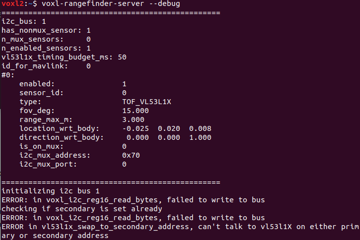
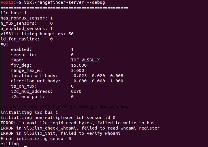
But the rangefinder server in not running, even after starting the server. It is enabled but not running.

-
Can you detect the sensor on the I2C bus, e.g https://docs.modalai.com/voxl2-linux-user-guide/#i2cdetect-usage ?
-
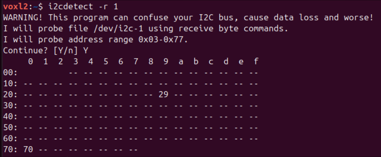
@modaltb It is not detecting any sensors, I check the sensor with another FC with PX4 which support VL53L1X and it was detected there.
-
what about with
i2cdetect -r -y 1
-
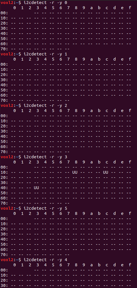
@modaltb I tried detecting in all i2c bus, 0 to 5, it wasn't detected, I got three devices in 4, but it was UU and I think it is the cameras.
-
-
-
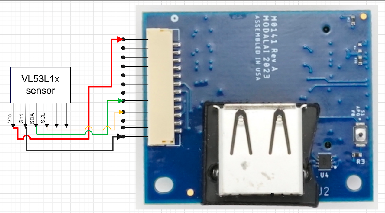
This is the wiring diagram of the sensor with the USB Expansion Board.
-
@modaltb Is there any specific SDK we could check for the working of Range-Finder with?
-
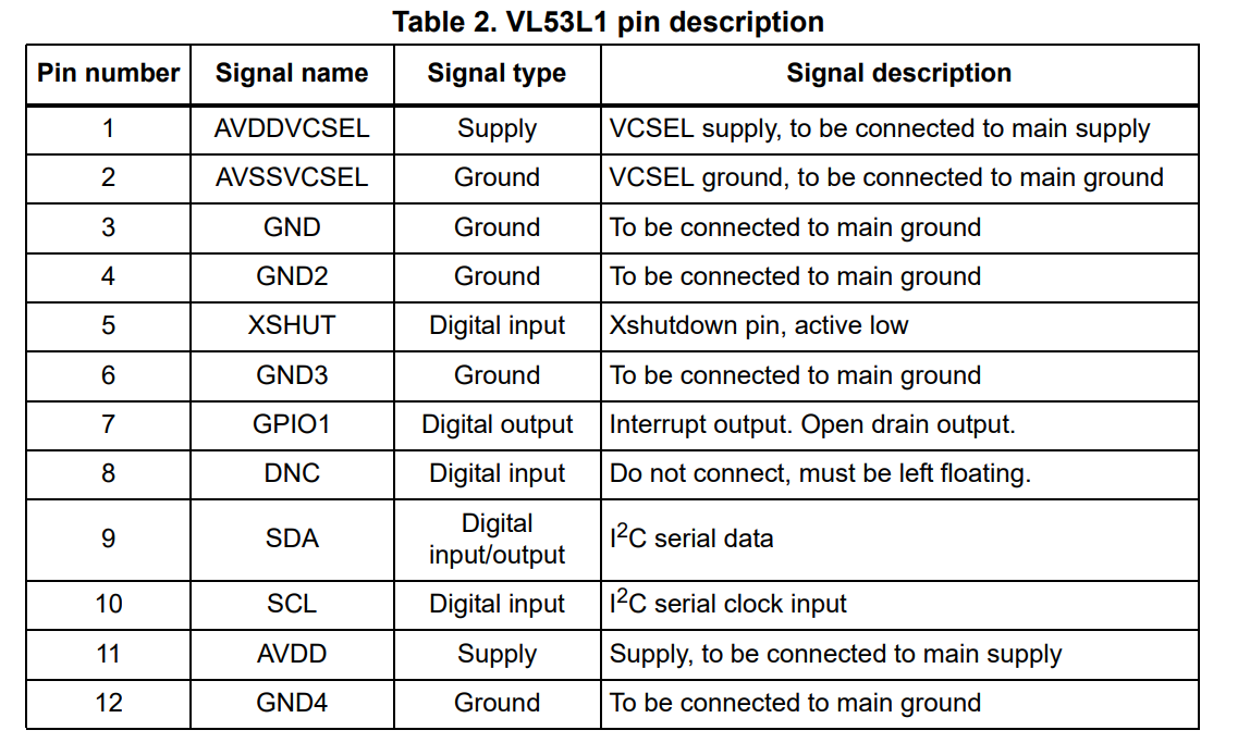
@Jetson-Nano are you using our M0070 board like this? https://docs.modalai.com/rangefinders/#single-rangefinder-using-m0141-expansion-board
Or custom? If custom check pin 5, which on our M0070 board is pulled up to 3.3VDC.
-
@modaltb I'm using M0141 expansion board.
-
@Jetson-Nano what is the VL53L1X on?
-
@modaltb is connected on J5 port of M0141.
-
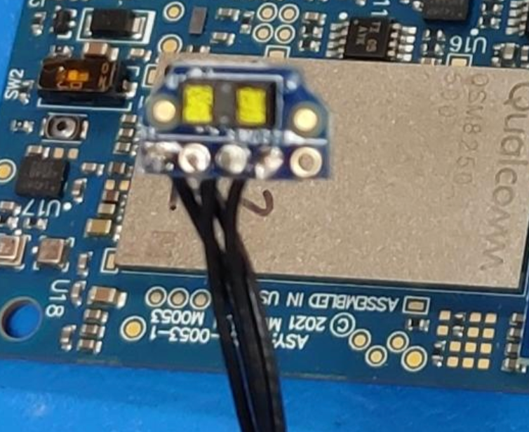
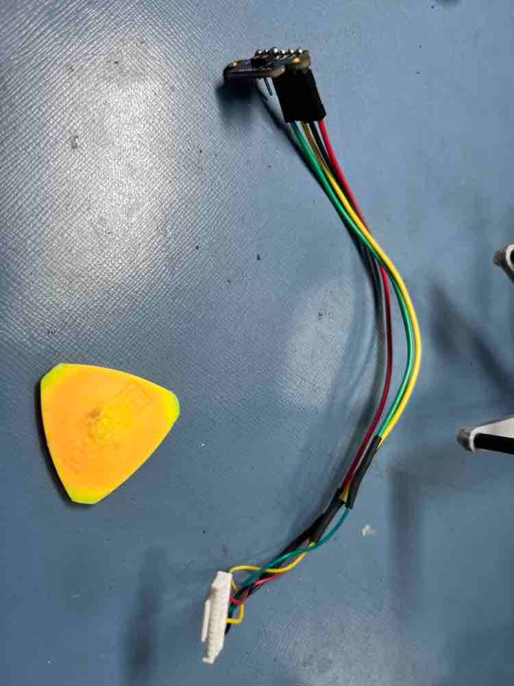
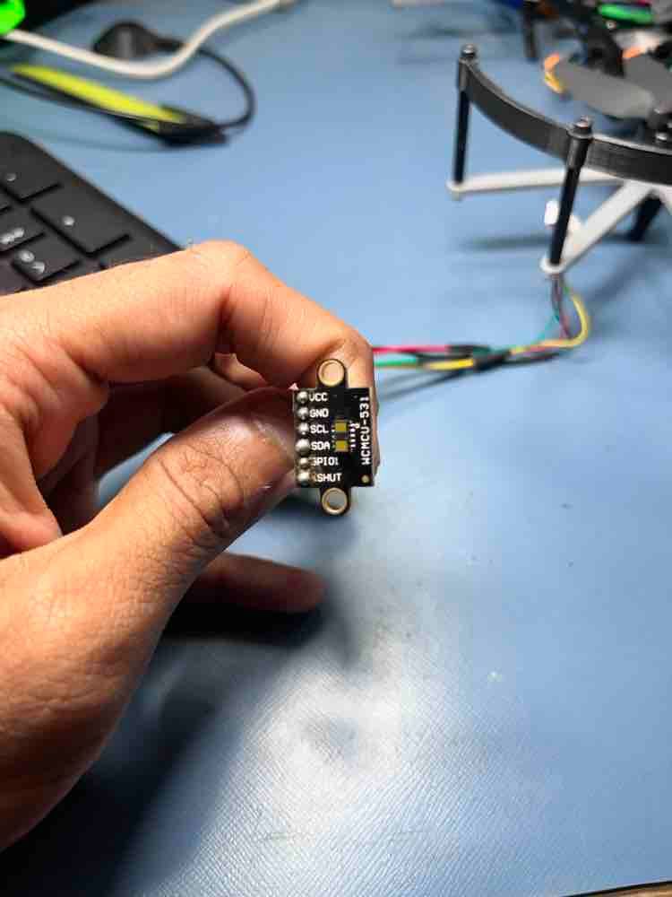
@Jetson-Nano can you take a picture? for example, we make a M0070 board that has this sensor on it. Are you making your own carrier board for the sensor?
-
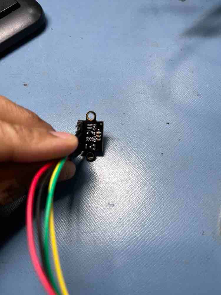
@modaltb This is our setup,
-
HI @Jetson-Nano
We have not seen that module before.
Is there a product link you can share so we can investigate for voltage and signal compatibility?Thanks!
-
@Vinny @modaltb Here is the link of the product
https://www.ktron.in/product/vl53l1x-laser-ranging-module-tof/
Thanks!
-
Thanks @Jetson-Nano
Can you help us find schematics?
I do not know what these parts are doing and could be leading to some of your issues...
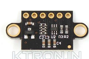
That site only has the link for the original datasheet.
Without more detail, I cannot offer much help aside from speculation.Thanks!
-
@Vinny I was not able to get the schematics. But when I tested this sensor with a Pixhawk flight controller running PX4, I was able to get it working on I2C.
-
Hi @Jetson-Nano
Pixhawk ports are 5V voltage output, we provide 3.3V.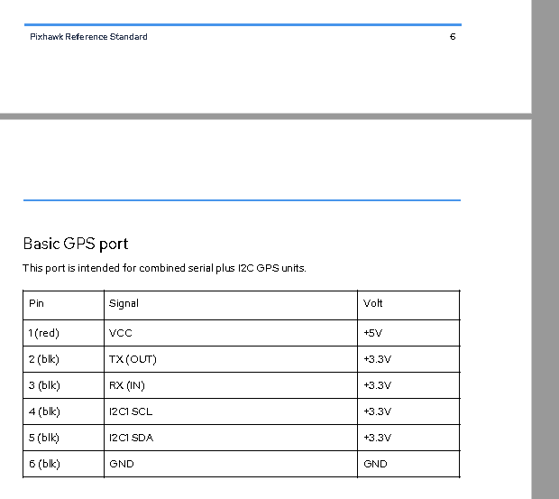
So, that data point does not help me from the HW viewpoint. I am assuming you knew you had 5V VREF from Pixhawk and converted to 3.3V.However, if we had the SCH of that module, that will tell me if they are actually trying to do voltage conversion of the I2C bus down to 1.8V (the default operating mode of these ST ToF units), which most likely is not compatible with our ports.
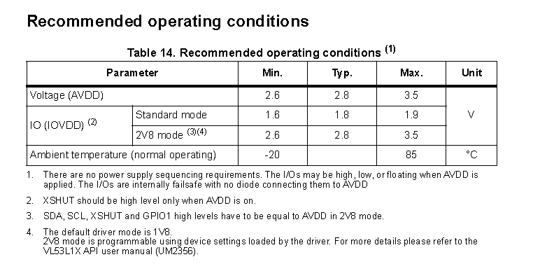
Most hobby electronics shops do not plan for all variations of translators, and most voltage translators do not like being cascaded. With a pixhawk, you are native 3.3V from the micro-controller w/o a level translator, so going through 1 level translator down to either 1.8V or 2.8V is no issue.
On VOXL 2 and VOXL 2 Mini, all of our JST ports have been translated up from 1.8V to 3.3V, which can limit the signal level translators we can work with since we end up with cascaded translators and that can be problematic if not designed correctly, especially I2C.
So, the SCH for that module is required for me to help further.
Sorry, but I can't do much else.
