
M0022 PWM Breakout Board: 8-Channel Output Pinout
-
Hardware: (board / drone / SKU, serial # if you have it): VOXL 2 IO (M0065) and M0022 PWM Breakout Board (Rev A, as shown in the diagram)
Software version: (paste the output of
voxl-version)Configuration / services: (paste the output of
voxl-inspect-services)What I am trying to do:
: I’m reviewing the wiring diagram that shows the M0022 PWM Breakout Board connected to the 10-pin J1 connector on the M0065. The PWM output header on the M0022 appears to have eight columns of three pins each.Could you confirm whether each column corresponds to one PWM channel and contains a PWM signal pin, a power pin, and a ground pin? If so, could you confirm the pin order within each column and which column corresponds to each channel (PWM 1–8)?
Are the power and ground pins shared across all eight columns? Is the power rail supplied through the M0065 J1 connector, or does it require an external supply?
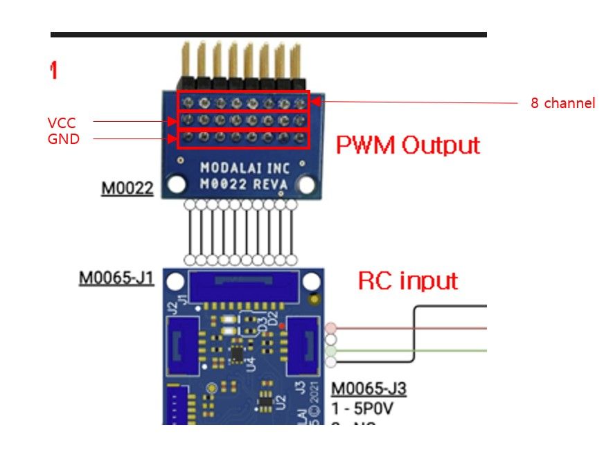
What actually happens: (error messages, behavior)Steps to reproduce:
Logs / pictures: (attach files; PX4 logs -> https://logs.px4.io)
-
Hardware: (board / drone / SKU, serial # if you have it): VOXL 2 IO (M0065) and M0022 PWM Breakout Board (Rev A, as shown in the diagram)
Software version: (paste the output of
voxl-version)Configuration / services: (paste the output of
voxl-inspect-services)What I am trying to do:
: I’m reviewing the wiring diagram that shows the M0022 PWM Breakout Board connected to the 10-pin J1 connector on the M0065. The PWM output header on the M0022 appears to have eight columns of three pins each.Could you confirm whether each column corresponds to one PWM channel and contains a PWM signal pin, a power pin, and a ground pin? If so, could you confirm the pin order within each column and which column corresponds to each channel (PWM 1–8)?
Are the power and ground pins shared across all eight columns? Is the power rail supplied through the M0065 J1 connector, or does it require an external supply?
What actually happens: (error messages, behavior)Steps to reproduce:
Logs / pictures: (attach files; PX4 logs -> https://logs.px4.io)
Hi,
Yes, each column is one channel. The full pinout is now in the VOXL 2 IO datasheet, under J1. For the M0022 Rev A:
Rows
- The row nearest the 10-pin J1 connector (silkscreen S) carries the PWM signals.
- The middle row is not connected.
- The row at the far board edge (silkscreen G) is ground.
Columns
The silkscreen numbers the columns 1 to 8. With the silkscreen readable and J1 toward you, column 1 is on the left, at the same end as J1 pin 1. Column n carries PWM channel n from VOXL 2 IO J1:
Column S row Middle row G row VOXL 2 IO J1 pin 1 PWM CH1 Not connected GND 2 2 PWM CH2 Not connected GND 3 3 PWM CH3 Not connected GND 4 4 PWM CH4 Not connected GND 5 5 PWM CH5 Not connected GND 6 6 PWM CH6 Not connected GND 7 7 PWM CH7 Not connected GND 8 8 PWM CH8 Not connected GND 9 Power and ground
- All eight G-row pins are tied together and to J1 pin 10 (GND).
- There is no power rail on the header. VOXL 2 IO J1 pin 1 (5P0V_BOOST) reaches the M0022 connector but is not connected on the board, and the middle row is not connected to anything.
- Power your ESCs or servos from their own supply. 5P0V_BOOST is a low-power reference only and must not power ESCs or servos: VOXL 2 IO datasheet, J1.
-
 V Vinny has marked this topic as solved

Reading along? Create a free ModalAI Forum account to join in.
With an account you can reply, ask your own question, get an email when a ModalAI engineer answers, and mark the reply that solved it. Your place in each thread is saved between visits.
Questions about VOXL, Flight Core, ESCs and ModalAI drones are answered here by the engineers who build them.
Register Login