
Starling Hires camera extrinsics
-
@Darshit-Desai, TOF has a rotation of 180 because it is actually oriented vertically inside the front of the vehicle
@Alex-Kushleyev And how about the body frame's location? As per my measurements from the CAD for the translations of ToF and hires it should be at centroid of the drone, is it the same?
-
@Darshit-Desai, TOF has a rotation of 180 because it is actually oriented vertically inside the front of the vehicle
Yes coordinates wrt to body should be measured wrt to center of the drone with x=forward, y=right and z= down. So your camera will be in front (that is x will be positive).. and so on (similar how TOF translation works). It seems the body to tof translation for TOF above (0.1,0,0) is approximate based on numbers being exactly zero

-
Yes coordinates wrt to body should be measured wrt to center of the drone with x=forward, y=right and z= down. So your camera will be in front (that is x will be positive).. and so on (similar how TOF translation works). It seems the body to tof translation for TOF above (0.1,0,0) is approximate based on numbers being exactly zero
You should get the translation from CAD between the center of the body (which can be estimated by an intersection of lines connecting two motor pairs) and the center of the hires camera module. You will get the 3 numbers and make sure you apply them correctly using the XYZ convention that the body uses (which may be different from the convention used in CAD viewer)
-
@Moderator
While this are the current extrinsics inside the starling drone, with some camera called lepton0_raw which is not present onboard the drone/** * The file is constructed as an array of multiple extrinsic entries, each * describing the relation from one parent to one child. Nothing stops you from * having duplicates but this is not advised. * * The rotation is stored in the file as a Tait-Bryan rotation sequence in * intrinsic XYZ order in units of degrees. This corresponds to the parent * rolling about its X axis, followed by pitching about its new Y axis, and * finally yawing around its new Z axis to end up aligned with the child * coordinate frame. * * Note that we elect to use the intrinsic XYZ rotation in units of degrees for * ease of use when doing camera-IMU extrinsic relations in the field. This is * not the same order as the aerospace yaw-pitch-roll (ZYX) sequence as used by * the rc_math library. However, since the camera Z axis points out the lens, it * is helpful for the last step in the rotation sequence to rotate the camera * about its lens after first rotating the IMU's coordinate frame to point in * the right direction by Roll and Pitch. * * The Translation vector should represent the center of the child coordinate * frame with respect to the parent coordinate frame in units of meters. * * The parent and child name strings should not be longer than 63 characters. * * The relation from Body to Ground is a special case where only the Z value is * read by voxl-vision-hub and voxl-qvio-server so that these services know the * height of the drone's center of mass (and tracking camera) above the ground * when the drone is sitting on its landing gear ready for takeoff. * * See https://docs.modalai.com/configure-extrinsics/ for more details. **/ { "name": "starling_v2_voxl2", "extrinsics": [{ "parent": "imu_apps", "child": "tracking", "T_child_wrt_parent": [0.0229, 0.006, 0.023], "RPY_parent_to_child": [0, 45, 90] }, { "parent": "body", "child": "imu_apps", "T_child_wrt_parent": [0.0407, -0.006, -0.0188], "RPY_parent_to_child": [0, 0, 0] }, { "parent": "body", "child": "tof", "T_child_wrt_parent": [0.068, -0.0116, -0.0168], "RPY_parent_to_child": [0, 90, 180] }, { "parent": "body", "child": "lepton0_raw", "T_child_wrt_parent": [-0.06, 0, 0.01], "RPY_parent_to_child": [0, 0, 90] }, { "parent": "body", "child": "ground", "T_child_wrt_parent": [0, 0, 0.0309], "RPY_parent_to_child": [0, 0, 0] }] }@Darshit-Desai said in Starling Hires camera extrinsics:
}, {
"parent": "body",
"child": "tof",
"T_child_wrt_parent": [0.068, -0.0116, -0.0168],
"RPY_parent_to_child": [0, 90, 180]Actually @Alex-Kushleyev you saw the wrong file, I later found this inisde voxlextrinsics conf in voxl2 starling its not exactly zero its some value. Based on that I measured using the coordinate convention you mentioned and figured that the centroid of the drone frame would be the origin of the body frame's coordinate axis
-
@Darshit-Desai said in Starling Hires camera extrinsics:
}, {
"parent": "body",
"child": "tof",
"T_child_wrt_parent": [0.068, -0.0116, -0.0168],
"RPY_parent_to_child": [0, 90, 180]Actually @Alex-Kushleyev you saw the wrong file, I later found this inisde voxlextrinsics conf in voxl2 starling its not exactly zero its some value. Based on that I measured using the coordinate convention you mentioned and figured that the centroid of the drone frame would be the origin of the body frame's coordinate axis
@Darshit-Desai OK, so is it clear now?
-
@Darshit-Desai, TOF has a rotation of 180 because it is actually oriented vertically inside the front of the vehicle
@Alex-Kushleyev said in Starling Hires camera extrinsics:
actually oriented vertically inside the front of the vehicle
What does this mean? Is it rotated somehow by 90 degrees along the z axis?
-
@Alex-Kushleyev said in Starling Hires camera extrinsics:
actually oriented vertically inside the front of the vehicle
What does this mean? Is it rotated somehow by 90 degrees along the z axis?
@Darshit-Desai , the TOF sensor looks like this https://www.modalai.com/products/voxl-dk-tof, it is shown in horizontal (normal) orientation. You can see in Starling that it is in vertial orientation (https://docs.modalai.com/starling-v2/)
-
@Darshit-Desai , the TOF sensor looks like this https://www.modalai.com/products/voxl-dk-tof, it is shown in horizontal (normal) orientation. You can see in Starling that it is in vertial orientation (https://docs.modalai.com/starling-v2/)
@Alex-Kushleyev Oh yes now I got it thanks
-
@Alex-Kushleyev Oh yes now I got it thanks
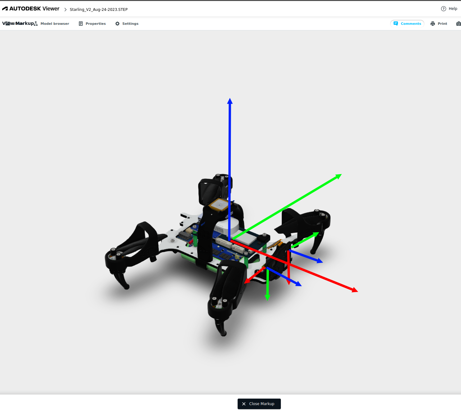
@Alex-Kushleyev just a sanity check for my understanding in the below markup I have considered MAVROS FLU (I've not considered the PX4 frame since I will be using mavros) frame as the reference frame and the rest of the tof and hires frames are shown below, is the tof frame represented correctly?
ToF frame is the smaller axes i.e., one on the top right side and hires is on the bottom left
-
@Alex-Kushleyev just a sanity check for my understanding in the below markup I have considered MAVROS FLU (I've not considered the PX4 frame since I will be using mavros) frame as the reference frame and the rest of the tof and hires frames are shown below, is the tof frame represented correctly?
ToF frame is the smaller axes i.e., one on the top right side and hires is on the bottom left
@Darshit-Desai , yes i believe you are showing the TOF and Hires camera local frames correctly.
As for the vehicle, the convention we normally use is FRD, but since you mentioned that you are assuming FLU in your case, that also looks correct.

Reading along? Create a free ModalAI Forum account to join in.
With an account you can reply, ask your own question, get an email when a ModalAI engineer answers, and mark the reply that solved it. Your place in each thread is saved between visits.
Questions about VOXL, Flight Core, ESCs and ModalAI drones are answered here by the engineers who build them.
Register Login