Unable to configure LTE modem
-
Hi,
I purchased the LTE V2 Pro with Sierra North America modem installed (https://www.modalai.com/collections/blue-uas-framework-components/products/m0130-3?variant=48186331726128). I am trying to set it up on my VOXL2 with a Canadian sim card from Rogers. I know the SIM card works (and APN is correct) since I have used it in another Quectel modem.
I run the "voxl-configure-modem" command and set the following:
- Type of modem: 1) v2
- connect to ModalLink: 2) no
- APN: 7) custom
- custom APN: lteinternet.apn
- modem region: 1) Americas
After this it just gets stuck at "Waiting for ttyUSB2..." and does not proceed further.
I have tried this a couple of times but without any success. Previously I was using a wifi dongle connected via the USB3.0/UART expander. I have removed it to plug in the LTE modem.
Kindly help to set me up with the LTE modem. Thanks.
-
@h3robotics It seems as though the modem itself is not being detected. Can you ensure that the add-on board is fully seated onto the VOXL and that both connectors are fully connected?
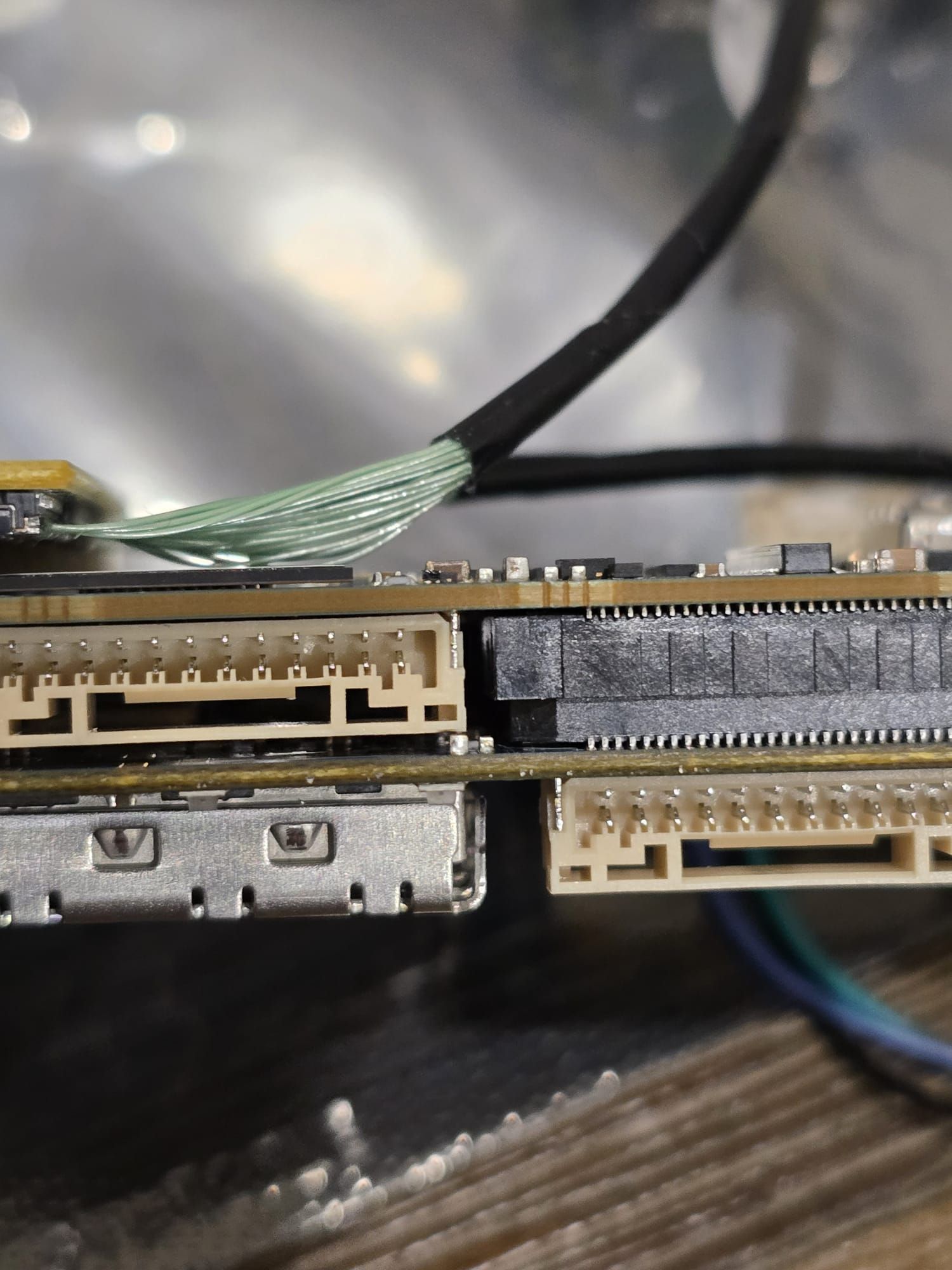
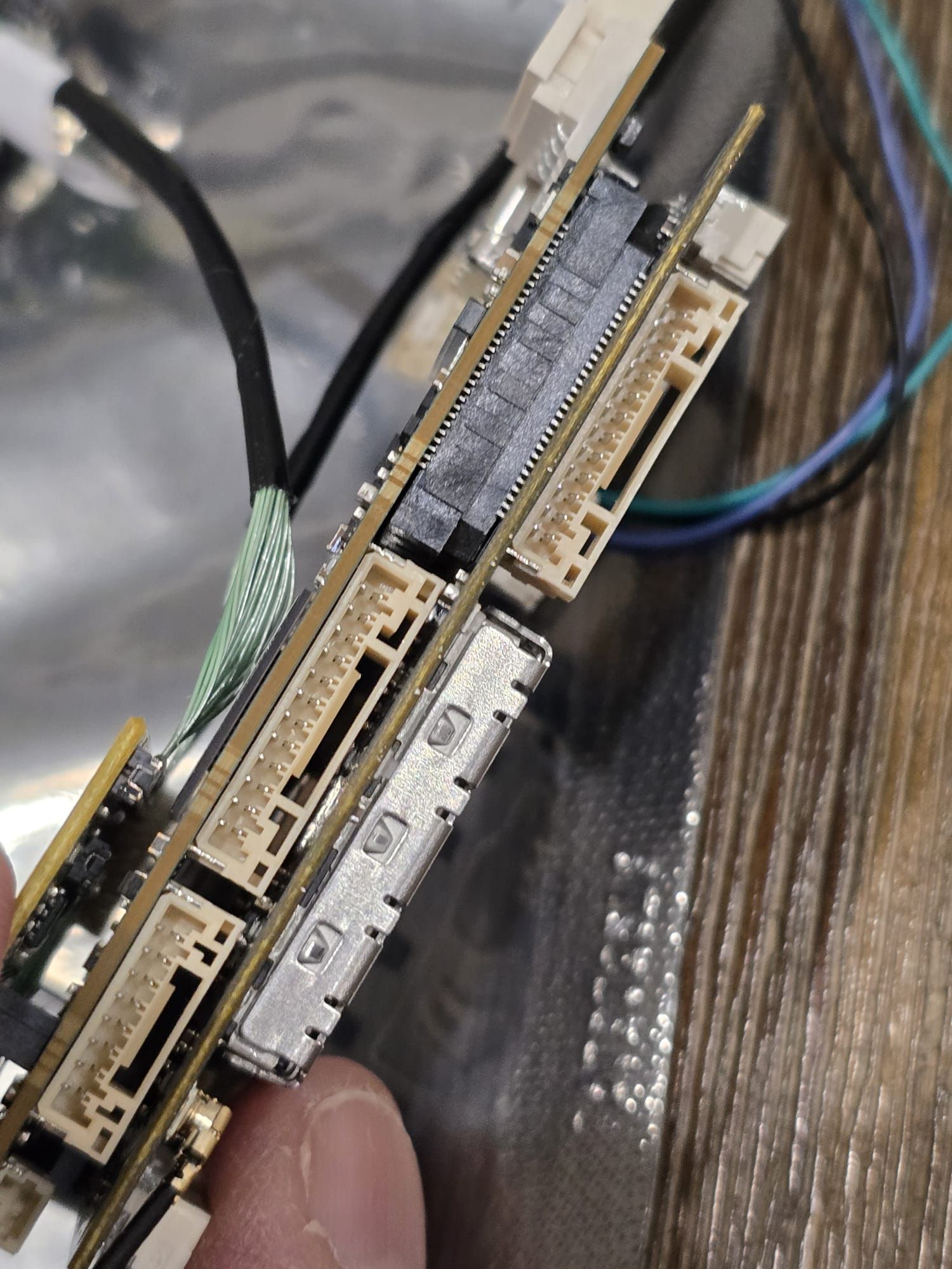
@tom when I was plugging in the modem, it did seem that the J1 connector does not go all the way in. But it is because of some small resistors that don't let the LTE modem seat completely.
I am attaching some pictures. Pic 1 and 2 shows the J1 connector side and the small resistor components.
Let me know if there is a solution to this

-
@tom when I was plugging in the modem, it did seem that the J1 connector does not go all the way in. But it is because of some small resistors that don't let the LTE modem seat completely.
I am attaching some pictures. Pic 1 and 2 shows the J1 connector side and the small resistor components.
Let me know if there is a solution to this
@h3robotics , the clearance is indeed very tight between the small capacitor and the beige 12-pin JST GH connector. However, in fully seated position of the add-on board into VOXL2, the JST GH connector does not touch the capacitor - your image shows the fully seated connection with slight clearance.
Alex
-
@h3robotics , the clearance is indeed very tight between the small capacitor and the beige 12-pin JST GH connector. However, in fully seated position of the add-on board into VOXL2, the JST GH connector does not touch the capacitor - your image shows the fully seated connection with slight clearance.
Alex
@Alex-Kushleyev I agree. When I put in the USB3/UART Add on board, I see that there is some clearance b/w the JST connector and the LTE board.
So it looks like the LTE modem is seated in properly. Looking forward to a solution to my problem of LTE setup")
-
@Alex-Kushleyev I agree. When I put in the USB3/UART Add on board, I see that there is some clearance b/w the JST connector and the LTE board.
So it looks like the LTE modem is seated in properly. Looking forward to a solution to my problem of LTE setup -
@h3robotics If the hardware is all good you should see the Sierra wireless device enumerate with
lsusband well as the network interface,wwan0enumerate when you checkifconfig@tom can you look at this topic I just created. It turns out I was wiring the 4-in-1 ESC wrong as per a wiring diagram in the documentation.
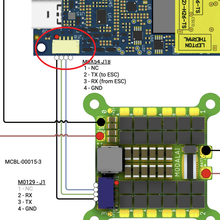
Error in VOXL mini 4 in 1 ESC diagram
Hi, I am having strange issues with the VOXL2. I had hooked it up with a 4-in-1 mini ESC using the diagram here: https://docs.modalai.com/images/d0014/CWD-D0...
ModalAI Forum (forum.modalai.com)
-
@tom can you look at this topic I just created. It turns out I was wiring the 4-in-1 ESC wrong as per a wiring diagram in the documentation.
Error in VOXL mini 4 in 1 ESC diagram
Hi, I am having strange issues with the VOXL2. I had hooked it up with a 4-in-1 mini ESC using the diagram here: https://docs.modalai.com/images/d0014/CWD-D0...
ModalAI Forum (forum.modalai.com)
@h3robotics , I believe you are correct that there is an error in the diagram. We will fix the diagram asap and work with you to make things right. Please give us a chance to evaluate what actually happens if the boards are connected in the way our diagram shows. Basically, it seems like the 3.3V from VOXL2 would be shorted to the GND on the ESC, but it needs further analysis.
-
@h3robotics , I believe you are correct that there is an error in the diagram. We will fix the diagram asap and work with you to make things right. Please give us a chance to evaluate what actually happens if the boards are connected in the way our diagram shows. Basically, it seems like the 3.3V from VOXL2 would be shorted to the GND on the ESC, but it needs further analysis.
@h3robotics , are you able to confirm ESC functionality without VOXL2 by connecting it to a power supply and usb-to-serial adapter (GND, RX, TX) to a Linux workstation? You can use
voxl-esctools to scan and test spin the ESC: https://gitlab.com/voxl-public/voxl-sdk/utilities/voxl-esc/-/tree/master/voxl-esc-tools?ref_type=heads#scanning-for-escsAlso, as you connect the ESC to a power supply (lets say 12V), please note the current draw, which should be around 20-30mA for an idling ESC (motors not spinning) without any load connected to its power regulator outputs. Also, you can verify the blue LED behavior as described here:

VOXL ESC FAQ
ModalAI technical documentation for VOXL and VOXL 2 Companion Computers for PX4 and ArduPilot Obstacle Avoidance and GPS-denied navigation, assembled in the USA
ModalAI Technical Docs (docs.modalai.com)
Furthermore, please use a volt meter to confirm that the voxl power output from the ESC is at 5.0V. This regulator feeds VOXL2 but is also used for the ESC itself (as the first stage of power regulation).
Alex
-
@h3robotics , are you able to confirm ESC functionality without VOXL2 by connecting it to a power supply and usb-to-serial adapter (GND, RX, TX) to a Linux workstation? You can use
voxl-esctools to scan and test spin the ESC: https://gitlab.com/voxl-public/voxl-sdk/utilities/voxl-esc/-/tree/master/voxl-esc-tools?ref_type=heads#scanning-for-escsAlso, as you connect the ESC to a power supply (lets say 12V), please note the current draw, which should be around 20-30mA for an idling ESC (motors not spinning) without any load connected to its power regulator outputs. Also, you can verify the blue LED behavior as described here:
VOXL ESC FAQ
ModalAI technical documentation for VOXL and VOXL 2 Companion Computers for PX4 and ArduPilot Obstacle Avoidance and GPS-denied navigation, assembled in the USA
ModalAI Technical Docs (docs.modalai.com)
Furthermore, please use a volt meter to confirm that the voxl power output from the ESC is at 5.0V. This regulator feeds VOXL2 but is also used for the ESC itself (as the first stage of power regulation).
Alex
@Alex-Kushleyev just to confirm that I need to use a USB-to-UART (TTLv3.3) cable and connect it to the UART port J1 of the ESC?
Thank you for working through this with me. Really appreciate the support! -
@h3robotics , are you able to confirm ESC functionality without VOXL2 by connecting it to a power supply and usb-to-serial adapter (GND, RX, TX) to a Linux workstation? You can use
voxl-esctools to scan and test spin the ESC: https://gitlab.com/voxl-public/voxl-sdk/utilities/voxl-esc/-/tree/master/voxl-esc-tools?ref_type=heads#scanning-for-escsAlso, as you connect the ESC to a power supply (lets say 12V), please note the current draw, which should be around 20-30mA for an idling ESC (motors not spinning) without any load connected to its power regulator outputs. Also, you can verify the blue LED behavior as described here:
VOXL ESC FAQ
ModalAI technical documentation for VOXL and VOXL 2 Companion Computers for PX4 and ArduPilot Obstacle Avoidance and GPS-denied navigation, assembled in the USA
ModalAI Technical Docs (docs.modalai.com)
Furthermore, please use a volt meter to confirm that the voxl power output from the ESC is at 5.0V. This regulator feeds VOXL2 but is also used for the ESC itself (as the first stage of power regulation).
Alex
@Alex-Kushleyev here are the results:
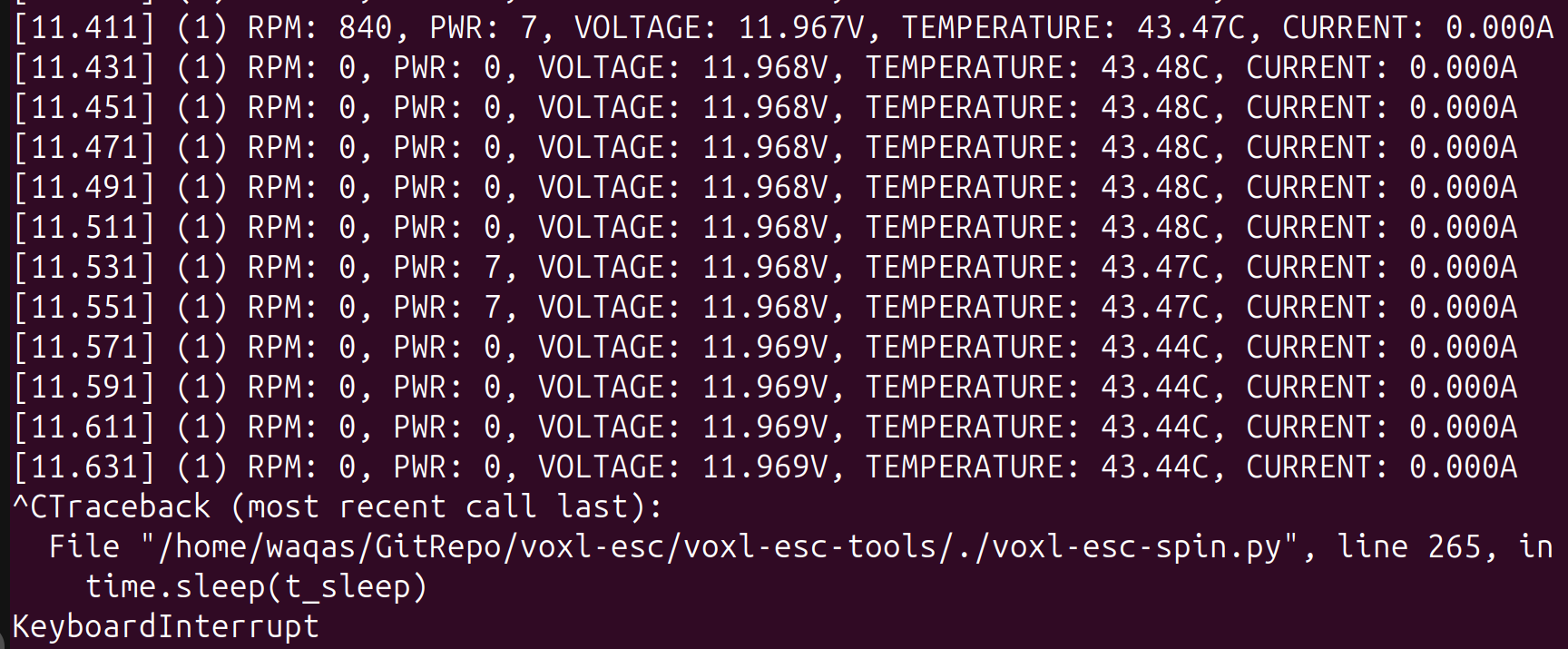
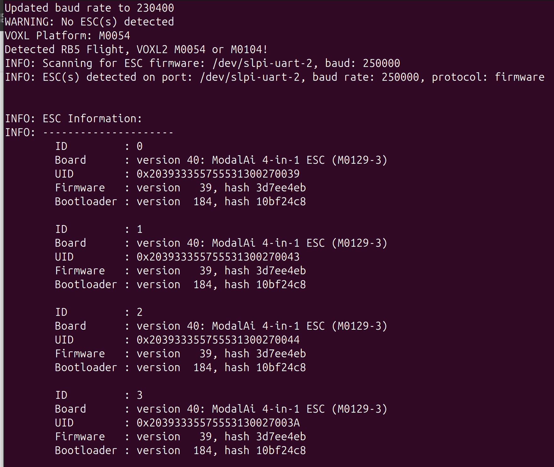
- I connected the ESC to a power supply (12V) and USB-UART(3.3v) cable. I was able to successfully scan and spin the ESC. See screenshots below:
I did not have any motors connected to the ESC but I did the spin test. I did see the current on my power supply jump from 38mA to ~55mA and all four LEDs were blinking blue.
-
When idle (ESC not spinning), the power supply was showing a current between 36mA - 38mA.
-
On bootup, the ESC blue LEDs rapidly flash for 1 s and then 2-3 blue blinks and then no blinking. When I spin the ESCs, the blue LEDs start blinking maybe once every second.
-
Using a voltmeter, I can see 5V on the power output.
Let me know the next steps
- I connected the ESC to a power supply (12V) and USB-UART(3.3v) cable. I was able to successfully scan and spin the ESC. See screenshots below:
-
@Alex-Kushleyev here are the results:
- I connected the ESC to a power supply (12V) and USB-UART(3.3v) cable. I was able to successfully scan and spin the ESC. See screenshots below:
I did not have any motors connected to the ESC but I did the spin test. I did see the current on my power supply jump from 38mA to ~55mA and all four LEDs were blinking blue.
-
When idle (ESC not spinning), the power supply was showing a current between 36mA - 38mA.
-
On bootup, the ESC blue LEDs rapidly flash for 1 s and then 2-3 blue blinks and then no blinking. When I spin the ESCs, the blue LEDs start blinking maybe once every second.
-
Using a voltmeter, I can see 5V on the power output.
Let me know the next steps
@h3robotics , Thanks for running the test. Yes, 3.3V TTL signal is correct, since ESC uses 3.3V signal levels.
It looks like the ESC test is good so far (as much as we can see without spinning)
Next I would suggest the following:
- unplug the LTE add-on board from VOXL2
- plug in power from the mini ESC into VOXL2
- plug in correct UART cable between VOXL2 and mini ESC
- test the ESC from VOXL2:
adb shell
systemctl stop voxl-px4
cd /usr/share/modalai/voxl-esc-tools
./voxl-esc-scan.py
./voxl-esc-spin.py --id 255 --power 0
(the last command will not spin the motors but will print out the voltage and current).
Also while VOXL2 is running, please double check the 5V (going to VOXL2) is still 5V.
Alex
- I connected the ESC to a power supply (12V) and USB-UART(3.3v) cable. I was able to successfully scan and spin the ESC. See screenshots below:
-
@h3robotics , Thanks for running the test. Yes, 3.3V TTL signal is correct, since ESC uses 3.3V signal levels.
It looks like the ESC test is good so far (as much as we can see without spinning)
Next I would suggest the following:
- unplug the LTE add-on board from VOXL2
- plug in power from the mini ESC into VOXL2
- plug in correct UART cable between VOXL2 and mini ESC
- test the ESC from VOXL2:
adb shell
systemctl stop voxl-px4
cd /usr/share/modalai/voxl-esc-tools
./voxl-esc-scan.py
./voxl-esc-spin.py --id 255 --power 0
(the last command will not spin the motors but will print out the voltage and current).
Also while VOXL2 is running, please double check the 5V (going to VOXL2) is still 5V.
Alex
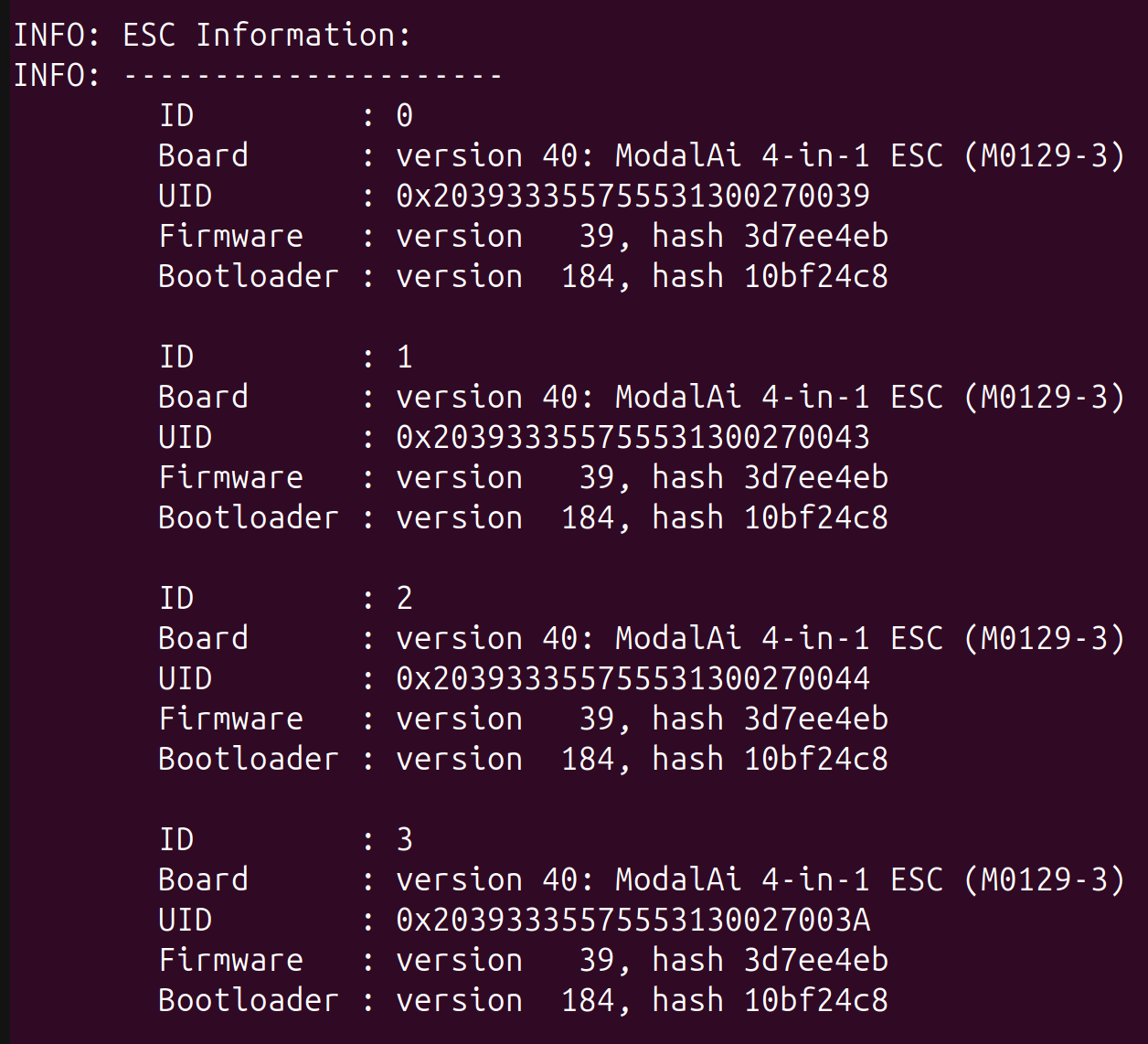
@Alex-Kushleyev I followed the steps. The ESC was detected in the scan:
and the run command executed as:
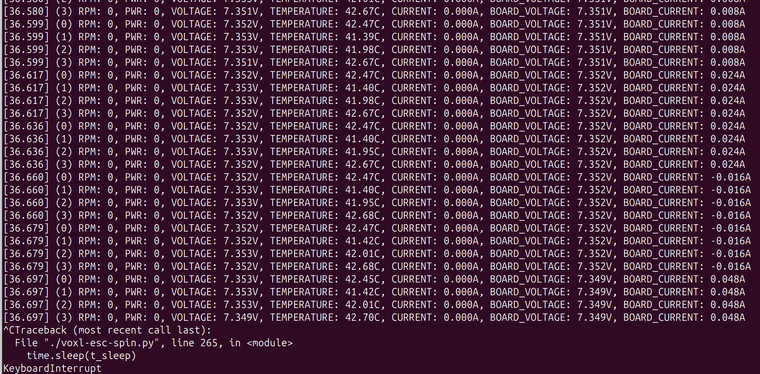
My power supply is at 7.4V since I intend to power the drone with 2S pack. In idle, the power supply shows ~132mA and during the spin test the power supply showed 135mA - 148mA.
- Also the power output is 5V at the ESC when VOXL2 is connected.
-
@Alex-Kushleyev I followed the steps. The ESC was detected in the scan:
and the run command executed as:
My power supply is at 7.4V since I intend to power the drone with 2S pack. In idle, the power supply shows ~132mA and during the spin test the power supply showed 135mA - 148mA.
- Also the power output is 5V at the ESC when VOXL2 is connected.
@h3robotics , OK great, so far it seems like everything is working properly. The M0129 current sensing is accurate to within few hundred mA (because the range is very large, up to 100A+), so it is OK that it is not quite matching up with the 135mA actual current draw.
Is there any indication that VOXL2 is not working properly so far?
One more thing to check.. since there was a possibility of a short of 3.3V coming from VOXL2 to GND, let's check that. You can test it at VOXL2 pin 1 on J18 or also pin1 on J10 (https://docs.modalai.com/voxl2-connectors/#j18-uart-esc). You could plug in a JST GH connector into either port (maybe J10 is easier, since J18 is populated by the ESC connection) and carefully check voltage present between pin1 and GND.
I can see that 3.3V is fed into the LTE Modem board, so if 3.3V is not present, this would be an issue.
Alex
-
@h3robotics , OK great, so far it seems like everything is working properly. The M0129 current sensing is accurate to within few hundred mA (because the range is very large, up to 100A+), so it is OK that it is not quite matching up with the 135mA actual current draw.
Is there any indication that VOXL2 is not working properly so far?
One more thing to check.. since there was a possibility of a short of 3.3V coming from VOXL2 to GND, let's check that. You can test it at VOXL2 pin 1 on J18 or also pin1 on J10 (https://docs.modalai.com/voxl2-connectors/#j18-uart-esc). You could plug in a JST GH connector into either port (maybe J10 is easier, since J18 is populated by the ESC connection) and carefully check voltage present between pin1 and GND.
I can see that 3.3V is fed into the LTE Modem board, so if 3.3V is not present, this would be an issue.
Alex
@Alex-Kushleyev it seems like after the wiring fix for the ESC, everything started to work properly.
- I measured the voltage b/w GND and pin 1 of J18 and it was around 3.3V.
- I also was able to configure the LTE modem without any issue.
- The ONLY problem I have now is that I don't see any battery voltage (or info) in voxl portal UI or QGround Control. I have the VOXL2 and Mini 4-in-1 ESC connected. I am under the impression that the ESC publishes battery info via the UART connection to the VOXL2 and the voxl-px4 service uses that to publish battery info? Am I correct? Am I missing something in the PX4 parameters or VOXL configuration?
Thank you for all your help!
-
@Alex-Kushleyev it seems like after the wiring fix for the ESC, everything started to work properly.
- I measured the voltage b/w GND and pin 1 of J18 and it was around 3.3V.
- I also was able to configure the LTE modem without any issue.
- The ONLY problem I have now is that I don't see any battery voltage (or info) in voxl portal UI or QGround Control. I have the VOXL2 and Mini 4-in-1 ESC connected. I am under the impression that the ESC publishes battery info via the UART connection to the VOXL2 and the voxl-px4 service uses that to publish battery info? Am I correct? Am I missing something in the PX4 parameters or VOXL configuration?
Thank you for all your help!
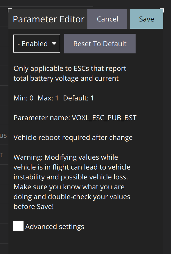
@h3robotics What is the setting of the VOXL_ESC_PUB_BST PX4 parameter? If you issue
px4-listener battery_statusfrom the command line what do you get? -
@h3robotics What is the setting of the VOXL_ESC_PUB_BST PX4 parameter? If you issue
px4-listener battery_statusfrom the command line what do you get?@Eric-Katzfey VOXL_ESC_PUB_BST = Enabled and px4-listener battery_status gives "never published".
-
@Eric-Katzfey VOXL_ESC_PUB_BST = Enabled and px4-listener battery_status gives "never published".
@h3robotics , did you set VOXL_ESC_PUB_BST to 1? it should be a 0 or 1, not "Enabled". please double check.
-
@h3robotics , did you set VOXL_ESC_PUB_BST to 1? it should be a 0 or 1, not "Enabled". please double check.
@Alex-Kushleyev No, it was default. I am using the latest QGround Control. Here are some images of the parameters.
All voxl related parameters:
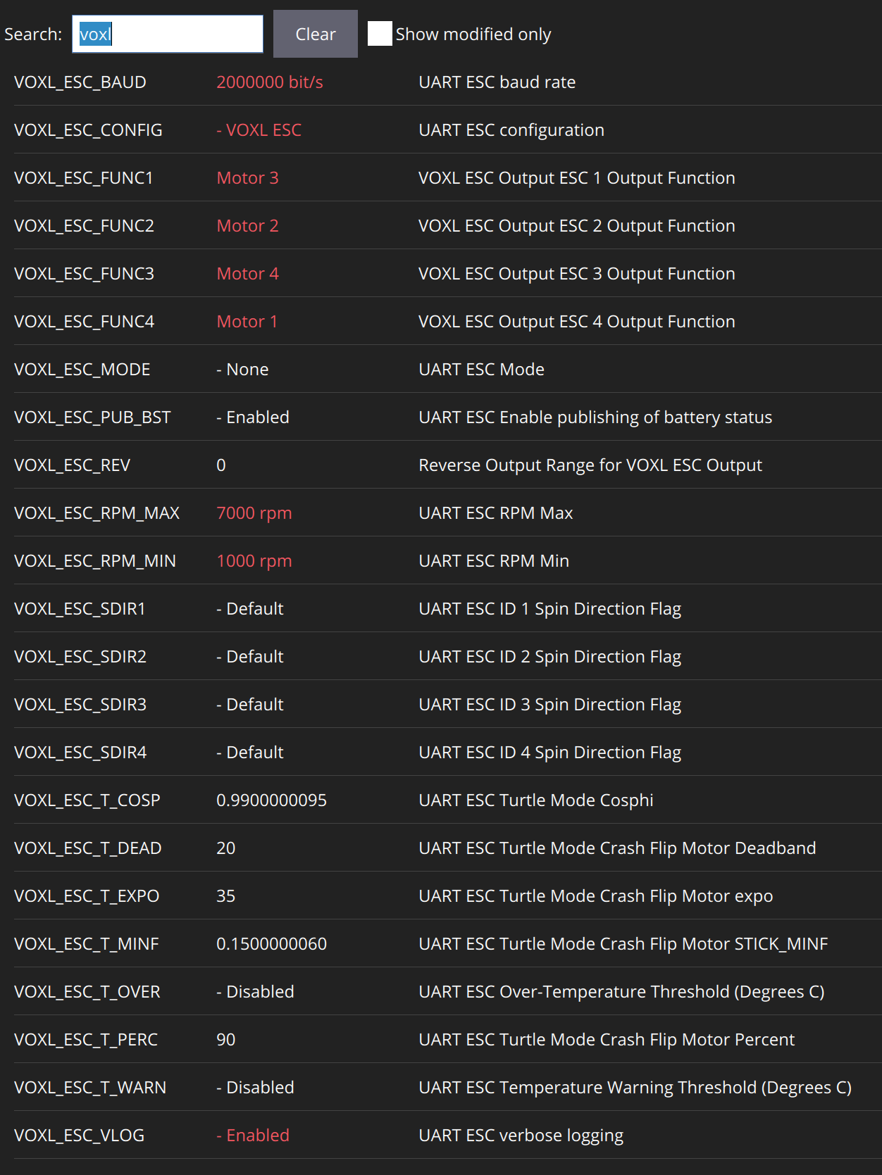
VOXL_ESC_PUB_BST:
I also double checked using manual entry:
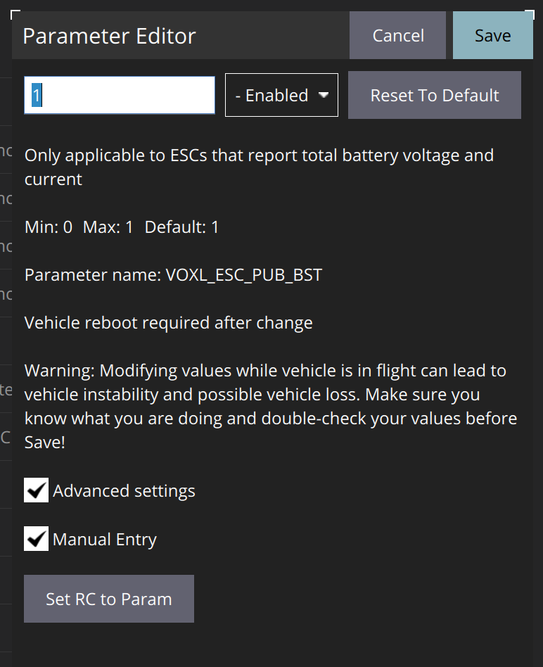
Let me know if that helps.
-
@Alex-Kushleyev No, it was default. I am using the latest QGround Control. Here are some images of the parameters.
All voxl related parameters:
VOXL_ESC_PUB_BST:
I also double checked using manual entry:
Let me know if that helps.
@h3robotics , I see, thanks for clarifying.
Is the ESC detected by PX4? What you can do is stop the px4 service using
systemctl stop voxl-px4and then run the px4 in a terminal :voxl-px4 -d, this will start px4 with an interactive px4 shell. You can also see debug prints from different modules that are starting up. Look for the voxl_esc module, it should say whether it was able to detect the ESC and, if so, then it will print some information about the ESC, such as its type, firmware version, etc.If the ESC is not detected, then you may have ESC parameters set up for incorrect baud rate (your PX4 params expect 2mbit, but perhaps your ESC is using lower bit rate, so you can update your ESC params to 2mbit). It is possible that your ESC is using 250K baud rate which is what it may ship with, so you can try 250K in PX4 to test that. If your ESC is set up for the lower bit rate, i would suggest updating that to at least 921600, or 1mbit or 2mbit in order to reduce delay and support the throughput for the ESC commands and telemetry.
Alex

Hello! It looks like you're interested in this conversation, but you don't have an account yet.
Getting fed up of having to scroll through the same posts each visit? When you register for an account, you'll always come back to exactly where you were before, and choose to be notified of new replies (either via email, or push notification). You'll also be able to save bookmarks and upvote posts to show your appreciation to other community members.
With your input, this post could be even better 💗
Register Login