Powering Servos from M0065/PWN Breakout
-
Hi Modal AI team,
My question is can the M0065/PWN Breakout power PWN connection for servo (signal, power, ground).
Is there a threshold for motor power requirements to where for smaller servos an external power source isn't but it is needed for larger servos? Can you clarify what is recommended?
Thanks!
@MattB69 ,
The 5V output on M0065 (10-pin connector with pwm outputs) should not be used to power any servos. The 5V signal is generated from 3.3V (coming from VOXL2) using a step-up converter, only capable of 80mA output).

VOXL 2 IO Datasheet
ModalAI technical documentation for VOXL and VOXL 2 Companion Computers for PX4 and ArduPilot Obstacle Avoidance and GPS-denied navigation, assembled in the USA
ModalAI Technical Docs (docs.modalai.com)
the 3.3V (which is coming from VOXL2), also should not be used to power servos, as that would be risking bringing down a major power rail on VOXL2.
Alex
-
@MattB69 ,
The 5V output on M0065 (10-pin connector with pwm outputs) should not be used to power any servos. The 5V signal is generated from 3.3V (coming from VOXL2) using a step-up converter, only capable of 80mA output).
VOXL 2 IO Datasheet
ModalAI technical documentation for VOXL and VOXL 2 Companion Computers for PX4 and ArduPilot Obstacle Avoidance and GPS-denied navigation, assembled in the USA
ModalAI Technical Docs (docs.modalai.com)
the 3.3V (which is coming from VOXL2), also should not be used to power servos, as that would be risking bringing down a major power rail on VOXL2.
Alex
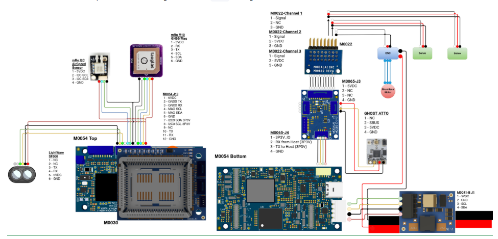
Thank you so much for the reply! Your answer makes sense. My only question is that the wiring diagram is misleading from the D0015 setup. It seems that for these servos that the wiring diagram does not show an external power source. Can you confirm that the diagram needs to updated, or is this an edge case (due to maybe a smaller servos used) where those servos can be power from VOXL2/IO/PWN power (for just the D0015 use case).
Or possibly that this diagram intentionally also shows compute logic and it needs an ESC. Can you also confirm if true that the ESC was initially left off diagram?
Take a look:
Source:
https://docs.modalai.com/voxl2-D0015/Once again thanks for responding, I absolutely love using your guys stuff - it makes everyone's stuff look bush league.
-Matt
-
Thank you so much for the reply! Your answer makes sense. My only question is that the wiring diagram is misleading from the D0015 setup. It seems that for these servos that the wiring diagram does not show an external power source. Can you confirm that the diagram needs to updated, or is this an edge case (due to maybe a smaller servos used) where those servos can be power from VOXL2/IO/PWN power (for just the D0015 use case).
Or possibly that this diagram intentionally also shows compute logic and it needs an ESC. Can you also confirm if true that the ESC was initially left off diagram?
Take a look:
Source:
https://docs.modalai.com/voxl2-D0015/Once again thanks for responding, I absolutely love using your guys stuff - it makes everyone's stuff look bush league.
-Matt
Hello @MattB69 ,
Sorry I made a mistake regarding the current rating of the step-up regulator. the 80mA number was for a very low input voltage (to the step-up regulator). with 3.3V intput to the step-up regulator, M0065 can support up to 350mA of output current at 5V, but we still do not recommend using it for powering servos.
So this means that our documentation for D0015 flight configuration is in conflict with documentation for M0065 board (which says use 5.0V for reference only).
Even though we have tested it in the D0015 configuration with "some" servos (i am not sure which ones were used), we still do not recommend powering servos using 5V from M0065. We will update the D0015 documentation.. Thanks for pointing it out!
Alex
-
Hello @MattB69 ,
Sorry I made a mistake regarding the current rating of the step-up regulator. the 80mA number was for a very low input voltage (to the step-up regulator). with 3.3V intput to the step-up regulator, M0065 can support up to 350mA of output current at 5V, but we still do not recommend using it for powering servos.
So this means that our documentation for D0015 flight configuration is in conflict with documentation for M0065 board (which says use 5.0V for reference only).
Even though we have tested it in the D0015 configuration with "some" servos (i am not sure which ones were used), we still do not recommend powering servos using 5V from M0065. We will update the D0015 documentation.. Thanks for pointing it out!
Alex
All is clear now. Thanks Alex!
-
All is clear now. Thanks Alex!
One more additional question about D0015 Diagram. The diagram shows that the Airspeed sensor board is being powered by 5V spliced from pin 1 on M0054 J19 connection.
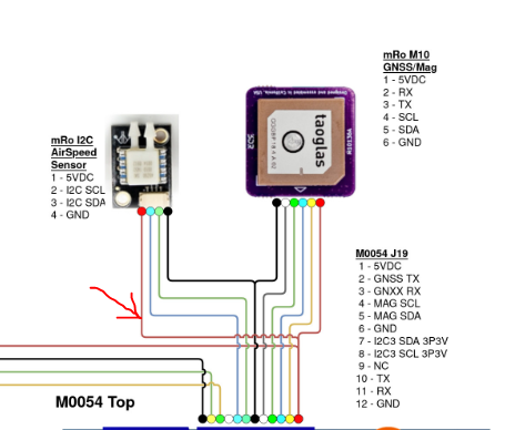
Also in the documentation, MCBL-00089 (Modal AI custom wire) is called out to be used for this connection of M0054 to GPS/LIDAR/Airspeed (see: https://docs.modalai.com/voxl2-D0015/)
My issue is that MCBL-00089 does not natively have this 5V connection pinned. See screenshot from MCBL-00089 purchase page. This also matches the MCBL-00089 that I bought.
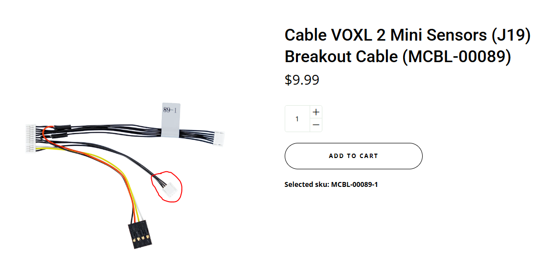
(Source: https://www.modalai.com/products/mcbl-00089?srsltid=AfmBOoqMsjLJnhWpaEPHMT_G8Yh8ix-NsRjJgGycprWXTBS-i_xqN8xY)Main question: Is the expectation that the user modifies MCBL-0089 to make this splice themselves? Or am I missing something here?
-
One more additional question about D0015 Diagram. The diagram shows that the Airspeed sensor board is being powered by 5V spliced from pin 1 on M0054 J19 connection.
Also in the documentation, MCBL-00089 (Modal AI custom wire) is called out to be used for this connection of M0054 to GPS/LIDAR/Airspeed (see: https://docs.modalai.com/voxl2-D0015/)
My issue is that MCBL-00089 does not natively have this 5V connection pinned. See screenshot from MCBL-00089 purchase page. This also matches the MCBL-00089 that I bought.
(Source: https://www.modalai.com/products/mcbl-00089?srsltid=AfmBOoqMsjLJnhWpaEPHMT_G8Yh8ix-NsRjJgGycprWXTBS-i_xqN8xY)Main question: Is the expectation that the user modifies MCBL-0089 to make this splice themselves? Or am I missing something here?
@Matt69 , good question. let me ask someone else to help with that
")
-
One more additional question about D0015 Diagram. The diagram shows that the Airspeed sensor board is being powered by 5V spliced from pin 1 on M0054 J19 connection.
Also in the documentation, MCBL-00089 (Modal AI custom wire) is called out to be used for this connection of M0054 to GPS/LIDAR/Airspeed (see: https://docs.modalai.com/voxl2-D0015/)
My issue is that MCBL-00089 does not natively have this 5V connection pinned. See screenshot from MCBL-00089 purchase page. This also matches the MCBL-00089 that I bought.
(Source: https://www.modalai.com/products/mcbl-00089?srsltid=AfmBOoqMsjLJnhWpaEPHMT_G8Yh8ix-NsRjJgGycprWXTBS-i_xqN8xY)Main question: Is the expectation that the user modifies MCBL-0089 to make this splice themselves? Or am I missing something here?
-
A UBEC was used for the servo connections, and they SHOULD NOT be powered from the board. We will update that drawing, thank you for pointing that out
-
As this was a first time build we did create that custom cable to deliver power to the airspeed sensor. We will make a note for that in the layout
Appreciate you pointing these things out so we can make those adjustments!
-
-
-
A UBEC was used for the servo connections, and they SHOULD NOT be powered from the board. We will update that drawing, thank you for pointing that out
-
As this was a first time build we did create that custom cable to deliver power to the airspeed sensor. We will make a note for that in the layout
Appreciate you pointing these things out so we can make those adjustments!
So to confirm - it is Modal AI's recommendation that the user modifies MCBL-0089 to allow for board (Voxl 2 Pin 1) to power airspeed sensor for this configuration? (Until you guys release a new custom cable for this use case?)
-
-
So to confirm - it is Modal AI's recommendation that the user modifies MCBL-0089 to allow for board (Voxl 2 Pin 1) to power airspeed sensor for this configuration? (Until you guys release a new custom cable for this use case?)
@Matt69 , yes you should splice the cable as needed. I will double check if we have plans to release a new cable, it will probably depend on the demand.
Alex
-
@Matt69 , yes you should splice the cable as needed. I will double check if we have plans to release a new cable, it will probably depend on the demand.
Alex
Thanks!
Hello! It looks like you're interested in this conversation, but you don't have an account yet.
Getting fed up of having to scroll through the same posts each visit? When you register for an account, you'll always come back to exactly where you were before, and choose to be notified of new replies (either via email, or push notification). You'll also be able to save bookmarks and upvote posts to show your appreciation to other community members.
With your input, this post could be even better 💗
Register Login