Skip to content
  • Categories
  • Recent
  • Tags
  • Popular
  • Users
  • Groups
Collapse
Brand Logo

ModalAI Forum

  1. ModalAI Support Forum
  2. VOXL Compute & Autopilot
  3. Flight Core v2
  4. FC2 schematic and board file

FC2 schematic and board file

Scheduled Pinned Locked Moved Flight Core v2
14 Posts 3 Posters 3.0k Views 1 Watching
  • Oldest to Newest
  • Newest to Oldest
  • Most Votes
Reply
  • Reply as topic
Log in to reply
This topic has been deleted. Only users with topic management privileges can see it.
  • D Offline
    D Offline
    daniel
    Contributor
    wrote on last edited by
    #1

    Hi there, can you please provide the FC2 schematic and board file? we'd like to measure/hooking CAN bus/UART/PWM etc signals during our development. Thanks.

    1 Reply Last reply
    0
    • J Offline
      J Offline
      Jacob Camarillo
      ModalAI Team
      wrote on last edited by
      #2

      Hi @daniel, you can find a functional description including drawings and a block diagram here. You can also find information regarding connectors/pinout on the next page of the documentation, here.

      D 1 Reply Last reply
      0
      • J Jacob Camarillo

        Hi @daniel, you can find a functional description including drawings and a block diagram here. You can also find information regarding connectors/pinout on the next page of the documentation, here.

        D Offline
        D Offline
        daniel
        Contributor
        wrote on last edited by
        #3

        Hi @Jacob-Camarillo, thanks for your information about FC V2 but I'd like to see more of peripheral ICs/Modules pins connection and power tree design, can ModalAI please share the schematic with me?

        Thanks,
        Daniel

        VinnyV 1 Reply Last reply
        0
        • D daniel

          Hi @Jacob-Camarillo, thanks for your information about FC V2 but I'd like to see more of peripheral ICs/Modules pins connection and power tree design, can ModalAI please share the schematic with me?

          Thanks,
          Daniel

          VinnyV Offline
          VinnyV Offline
          Vinny
          ModalAI Team
          wrote on last edited by
          #4

          Hi @daniel
          We do not have an open-source HW platform, so we do not share schematics publicly.
          If there is specific info missing on our tech docs page, please let us know. We provide an elaborate diagram in there which includes the power distribution and mux tree: https://docs.modalai.com/flight-core-datasheets-v2-functional-description/#block-diagram
          Our pin tables also provide all access points you should need: https://docs.modalai.com/flight-core-v2-datasheets-connectors/

          Thanks!
          Vinny

          1 Reply Last reply
          0
          • D Offline
            D Offline
            daniel
            Contributor
            wrote on last edited by
            #5

            Hi @Vinny , we have can bus no communication issue, according to J8 - CAN Bus Connector Notes CAN “Silent” pin (STBY) is controlled by STM32 PD15 pin (default pulled-LOW in hardware), can you please provide the STM32 PD15 pin's location or board file for our measurement?

            Thanks,
            Daniel

            VinnyV 1 Reply Last reply
            0
            • D daniel

              Hi @Vinny , we have can bus no communication issue, according to J8 - CAN Bus Connector Notes CAN “Silent” pin (STBY) is controlled by STM32 PD15 pin (default pulled-LOW in hardware), can you please provide the STM32 PD15 pin's location or board file for our measurement?

              Thanks,
              Daniel

              VinnyV Offline
              VinnyV Offline
              Vinny
              ModalAI Team
              wrote on last edited by
              #6

              Hi @daniel
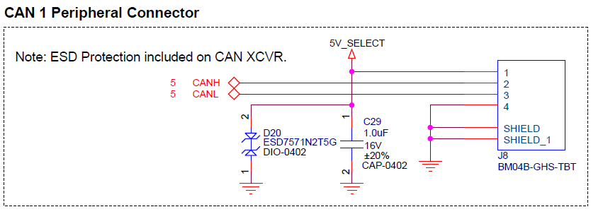
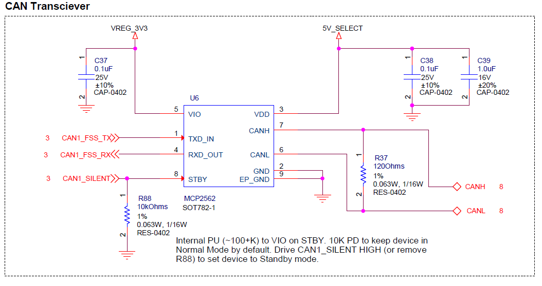
              Here is the SCH snippet of the CAN XCVR device and connector... note pin 8 is pulled LOW by default to keep it active. SW must drive the CAN1_SILENT pin HIGH to place it in STBY mode.

              3e8b5ab8-01c0-4ffb-a8ed-4412c2064593-image.png
              6488cf0d-5543-4c8d-a07a-980744663ee8-image.png

              Hope this helps!

              1 Reply Last reply
              0
              • D Offline
                D Offline
                daniel
                Contributor
                wrote on last edited by
                #7

                Thanks @Vinny , can you please also provide the PX4 detect/Monitor circuits? if possible using that monitor circuit to read the battery level through ADC1/ADC3 instead of can bus?

                VinnyV 1 Reply Last reply
                0
                • D daniel

                  Thanks @Vinny , can you please also provide the PX4 detect/Monitor circuits? if possible using that monitor circuit to read the battery level through ADC1/ADC3 instead of can bus?

                  VinnyV Offline
                  VinnyV Offline
                  Vinny
                  ModalAI Team
                  wrote on last edited by
                  #8

                  Hi @daniel
                  Our block diagram shows we have 4 ADC inputs exposed on a connector, J14, for general purpose use.
                  However, I'm not sure if it is linked in PX4 use or not:
                  https://docs.modalai.com/flight-core-v2-datasheets-connectors/#j14---external-spii2cadc

                  For the PX4 monitoring circuits, we do not recommend messing with those in any way. Those are basic 5V and 3.3V voltage detect circuits and ID settings, and I'm pretty sure PX4 will balk if those are re-purposed. However, we do show on the block diagram all pin assignments if you look carefully. If you are trying a so-called "bare metal" design (non-PX4, your own code through the ST32 Cube IDE), then do so at your own risk but we cannot offer any RMA service on boards modified from their intentional design.

                  D 1 Reply Last reply
                  0
                  • VinnyV Vinny

                    Hi @daniel
                    Our block diagram shows we have 4 ADC inputs exposed on a connector, J14, for general purpose use.
                    However, I'm not sure if it is linked in PX4 use or not:
                    https://docs.modalai.com/flight-core-v2-datasheets-connectors/#j14---external-spii2cadc

                    For the PX4 monitoring circuits, we do not recommend messing with those in any way. Those are basic 5V and 3.3V voltage detect circuits and ID settings, and I'm pretty sure PX4 will balk if those are re-purposed. However, we do show on the block diagram all pin assignments if you look carefully. If you are trying a so-called "bare metal" design (non-PX4, your own code through the ST32 Cube IDE), then do so at your own risk but we cannot offer any RMA service on boards modified from their intentional design.

                    D Offline
                    D Offline
                    daniel
                    Contributor
                    wrote on last edited by
                    #9

                    Hi @Vinny
                    Yes, I see the pin assignment on the block diagram, but I want to see the circuits of "basic 5V and 3.3V voltage detect circuits and ID settings" seem like those configs are important for PX4.

                    Can you please tell how many ways that FCv2 can get battery information? is it via I2C3 bus to read the battery information from power module? any other way?

                    Thanks!
                    Daniel

                    VinnyV 1 Reply Last reply
                    0
                    • D daniel

                      Hi @Vinny
                      Yes, I see the pin assignment on the block diagram, but I want to see the circuits of "basic 5V and 3.3V voltage detect circuits and ID settings" seem like those configs are important for PX4.

                      Can you please tell how many ways that FCv2 can get battery information? is it via I2C3 bus to read the battery information from power module? any other way?

                      Thanks!
                      Daniel

                      VinnyV Offline
                      VinnyV Offline
                      Vinny
                      ModalAI Team
                      wrote on last edited by
                      #10

                      HI @daniel
                      Yes, battery info is from the power module via I2C3.
                      The detect/ID circuits are part of our proprietary design that we cannot share over a public forum. Hence, we do not recommend you mess with the detect functions at all.
                      Hope that helps.

                      D 1 Reply Last reply
                      0
                      • VinnyV Vinny

                        HI @daniel
                        Yes, battery info is from the power module via I2C3.
                        The detect/ID circuits are part of our proprietary design that we cannot share over a public forum. Hence, we do not recommend you mess with the detect functions at all.
                        Hope that helps.

                        D Offline
                        D Offline
                        daniel
                        Contributor
                        wrote on last edited by
                        #11

                        Hi @Vinny,
                        Please advise the FCv2 MCU stm32h753ii for PCB stackup, how many layers of PCB? Is it need HDI or just normal PCB process?
                        Thanks!

                        VinnyV 1 Reply Last reply
                        0
                        • D daniel

                          Hi @Vinny,
                          Please advise the FCv2 MCU stm32h753ii for PCB stackup, how many layers of PCB? Is it need HDI or just normal PCB process?
                          Thanks!

                          VinnyV Offline
                          VinnyV Offline
                          Vinny
                          ModalAI Team
                          wrote on last edited by
                          #12

                          HI @daniel
                          That is part of design strategy that your Engineering team needs to decide when working with various parts and PCB Fab manufacturers. This is not something we can share (and even if we did, it would not be applicable).
                          Thanks!

                          1 Reply Last reply
                          0
                          • D Offline
                            D Offline
                            daniel
                            Contributor
                            wrote on last edited by
                            #13

                            Hi @Vinny ,
                            I have couple questions on FCv2 hardware, thank you!

                            1. what is the purpose of STM32 UART7 through level shifters (74LVCH2T45)? both VCCA and VCCB are same 3.3V domain?
                            2. J2 - where is VPP_STM connect to and what is the function?
                            3. J5 - why there is no level shifter on UART5?
                            4. J13 - Is that PM monitoring really need for FC? Can I just use a adc pin to monitor battery voltage through the divided resistors?
                            5. RGB1 LEDs are controlled by GPO PE3/4/5, please confirm which pin for witch color.
                              Thanks,
                              Daniel
                            VinnyV 1 Reply Last reply
                            0
                            • D daniel

                              Hi @Vinny ,
                              I have couple questions on FCv2 hardware, thank you!

                              1. what is the purpose of STM32 UART7 through level shifters (74LVCH2T45)? both VCCA and VCCB are same 3.3V domain?
                              2. J2 - where is VPP_STM connect to and what is the function?
                              3. J5 - why there is no level shifter on UART5?
                              4. J13 - Is that PM monitoring really need for FC? Can I just use a adc pin to monitor battery voltage through the divided resistors?
                              5. RGB1 LEDs are controlled by GPO PE3/4/5, please confirm which pin for witch color.
                                Thanks,
                                Daniel
                              VinnyV Offline
                              VinnyV Offline
                              Vinny
                              ModalAI Team
                              wrote on last edited by
                              #14

                              Hi @daniel
                              Please see responses below.

                              @daniel said in FC2 schematic and board file:

                              1. what is the purpose of STM32 UART7 through level shifters (74LVCH2T45)? both VCCA and VCCB are same 3.3V domain?

                              Yes, an early proto-type design had that port at 5V, so we had the level shifters. We then changed it to 3.3V for our production version, so technically the level shifters would not be needed, but it will give you longer cable drive range because of it.

                              1. J2 - where is VPP_STM connect to and what is the function?

                              You can get this info from any STM device spec. We (a programmer device) use it the way STM specifies

                              1. J5 - why there is no level shifter on UART5?

                              It is not needed. See response above.

                              1. J13 - Is that PM monitoring really need for FC? Can I just use a adc pin to monitor battery voltage through the divided resistors?

                              That feature is your choice. The power monitoring will be MUCH more accurate since we use a 16-bit device as highlighted here https://docs.modalai.com/power-module-v3-datasheet/ , and it is capable of coulomb counting if the PX4 drivers that can do that. There are tons of research articles out there about pure voltage monitoring vs coulomb counting, so we leave it to you to decide what works best for you.

                              1. RGB1 LEDs are controlled by GPO PE3/4/5, please confirm which pin for witch color.

                              We go in order of the port pins noted as "RGB", so PE3 is RED, PE4 is GREEN, PE5 is BLUE. All are "Active LOW" to Illuminate the LEDs.

                              Hope this helped!!

                              To me, based on all the questions you've been asking these past weeks, it seems as if you are designing your own version of HW that you want to be compatible with our FCv2 firmware.
                              If this is true, just let us know and we can try to assist you better. If you want a different form-factor for the board, that might be something we'd be interested in supporting if it helps you better. Just ask!
                              Feel free to use our contact page if you want the conversation to be less public: https://www.modalai.com/pages/contact-us

                              1 Reply Last reply
                              0

                              Hello! It looks like you're interested in this conversation, but you don't have an account yet.

                              Getting fed up of having to scroll through the same posts each visit? When you register for an account, you'll always come back to exactly where you were before, and choose to be notified of new replies (either via email, or push notification). You'll also be able to save bookmarks and upvote posts to show your appreciation to other community members.

                              With your input, this post could be even better 💗

                              Register Login
                              Reply
                              • Reply as topic
                              Log in to reply
                              • Oldest to Newest
                              • Newest to Oldest
                              • Most Votes


                              ModalAI
                              Categories Recent Tags ModalAI.com Docs
                              © 2026 ModalAI® · Accelerating autonomy for smaller, smarter, safer drones · Powered by NodeBB
                              • Login

                              • Don't have an account? Register

                              • Login or register to search.
                              • First post
                                Last post
                              0
                              • Categories
                              • Recent
                              • Tags
                              • Popular
                              • Users
                              • Groups