
Power In
-
Hello,
I am looking to create a carrier board for the VOXL2 utilizing the J3 and J5 IO, and had a couple questions.
- Power: I can see that there is power input on the J5 connector for 5V in, but I am slightly confused by the pinouts under J5 section. It appears that there is multiple 5V input pins.
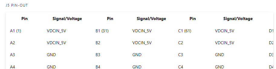 . I am not an electrical engineer. So, let me know if I need to bring in one on this to understand what these mean.
 - Mapping pins to paths on linux. I can see that with QUPs we can define what protocol different pins are doing. How do we then map those to a linux path (such as /dev/ttyS0 or something)
Thank you for the help, and please let me know if I need to seek outside resources/counsel to better understand these things. I am trained in software, but trying to better understand this. Thank you!
- Power: I can see that there is power input on the J5 connector for 5V in, but I am slightly confused by the pinouts under J5 section. It appears that there is multiple 5V input pins.
-
Hello,
I am looking to create a carrier board for the VOXL2 utilizing the J3 and J5 IO, and had a couple questions.
- Power: I can see that there is power input on the J5 connector for 5V in, but I am slightly confused by the pinouts under J5 section. It appears that there is multiple 5V input pins. . I am not an electrical engineer. So, let me know if I need to bring in one on this to understand what these mean.
- Mapping pins to paths on linux. I can see that with QUPs we can define what protocol different pins are doing. How do we then map those to a linux path (such as /dev/ttyS0 or something)
Thank you for the help, and please let me know if I need to seek outside resources/counsel to better understand these things. I am trained in software, but trying to better understand this. Thank you!
Hi @wilkinsaf
Please refer to this tech docs page and let me know if this helps!
https://docs.modalai.com/expansion-design-guide/
More specifically, these sections:
https://docs.modalai.com/expansion-design-guide/#5v-power-in-vs-5v-power-out
VDCIN_5V has 8 pins in order to meet the 6A current constraint we need.
So, any custom carrier card that intends to provide power TO Voxl2 must have a 6Amp supply and drive those 8 pins together.For the SW question, I'm not the expert, so hopefully this link helps...
https://docs.modalai.com/voxl2-linux-user-guide/And, as a teaser... we are in process of building this new board right now... working on the docs at this very moment (so some data is irrelevant as a copy->paste, but it'll be all updated in the next few days): https://docs.modalai.com/voxl2-dev-test-board/
This is the very first public announcement of this new test board. I have hooks in there to test 5V delivery from an external system. SCH will be posted later today
- Power: I can see that there is power input on the J5 connector for 5V in, but I am slightly confused by the pinouts under J5 section. It appears that there is multiple 5V input pins.
-
Hello,
I am looking to create a carrier board for the VOXL2 utilizing the J3 and J5 IO, and had a couple questions.
- Power: I can see that there is power input on the J5 connector for 5V in, but I am slightly confused by the pinouts under J5 section. It appears that there is multiple 5V input pins. . I am not an electrical engineer. So, let me know if I need to bring in one on this to understand what these mean.
- Mapping pins to paths on linux. I can see that with QUPs we can define what protocol different pins are doing. How do we then map those to a linux path (such as /dev/ttyS0 or something)
Thank you for the help, and please let me know if I need to seek outside resources/counsel to better understand these things. I am trained in software, but trying to better understand this. Thank you!
Hi @wilkinsaf
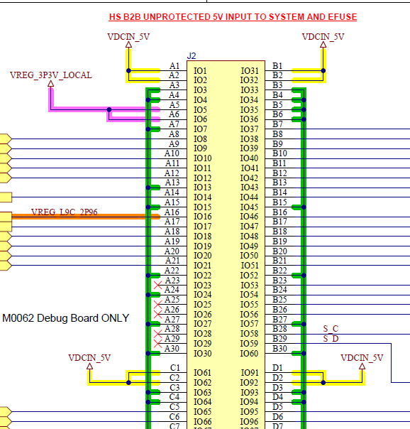
Our Schematic for the "B-Quad" (Voxl2 Developer Test Board, M0144) are live!!
https://docs.modalai.com/voxl2-dev-test-board-datasheet/#schematicsIn there, you can see an example of how to design the proper connections for powering Voxl2 from J5. VDCIN_5V would be from a 6A capable power supply on your host system (carrier board):
- Power: I can see that there is power input on the J5 connector for 5V in, but I am slightly confused by the pinouts under J5 section. It appears that there is multiple 5V input pins.


Reading along? Create a free ModalAI Forum account to join in.
With an account you can reply, ask your own question, get an email when a ModalAI engineer answers, and mark the reply that solved it. Your place in each thread is saved between visits.
Questions about VOXL, Flight Core, ESCs and ModalAI drones are answered here by the engineers who build them.
Register Login