
Motor Replacement Instructions Starling 2 Max
-
Hey all,
After an unfortunate crash the 2 front motors on our Starling 2 Max are damaged (they stick in one portion of the rotation) and need to be replaced. I have ordered 2 new Tmotor 2203.5 1500kv motors but it looks like the motor cables go under the main VOXL boards to the ESCs.
Are there any disassembly or repair instructions for the Starling 2 Max?
Kind regards,
GriffinP.S. Do not command the drone to do a position change with a simultaneous 1m xy reposition and a 2m z change. The drone commanded a 10m/s acceleration and flew into a wall
The starling 2 max datasheet lists the motors as 3000KV 1504 motors, the motors on the aircraft we have appear to be 1500kv not 3000kv. Which number is correct?
-
The starling 2 max datasheet lists the motors as 3000KV 1504 motors, the motors on the aircraft we have appear to be 1500kv not 3000kv. Which number is correct?
@tom Any updates or assistance available here? According to Motor Damaged @Jeremy-Schmidt is the best person to ask?
Kind regards,
Griffin -
@tom Any updates or assistance available here? According to Motor Damaged @Jeremy-Schmidt is the best person to ask?
Kind regards,
Griffin -
The starling 2 max datasheet lists the motors as 3000KV 1504 motors, the motors on the aircraft we have appear to be 1500kv not 3000kv. Which number is correct?
@griffin
For Starling MAX, the correct motor is the 2203.5 1500kv.Did you order them from us? We customize the length of the wires for the Starling MAX specifically, so an "off the shelf" version of that Tmotor will have shorter wires.
-
@griffin
For Starling MAX, the correct motor is the 2203.5 1500kv.Did you order them from us? We customize the length of the wires for the Starling MAX specifically, so an "off the shelf" version of that Tmotor will have shorter wires.
@Jeremy-Schmidt thanks for the response. Unfortunately, I didn't see the starling 2 max motors on the modalai website and ordered directly from a supplier. Is the cable adjustment difficult or tooling intensive? How would I order motors directly from you?
thanks,
Griffin -
@Jeremy-Schmidt thanks for the response. Unfortunately, I didn't see the starling 2 max motors on the modalai website and ordered directly from a supplier. Is the cable adjustment difficult or tooling intensive? How would I order motors directly from you?
thanks,
Griffin@griffin
To extend the wires, you only need to solder splice the correct length of extra wire.I'm looking into our custom version being available to you. Probably won't have an answer until the morning
-
@griffin Take a look at the drone and realize each motor has 3 wires and 3 pads on the ESC board they get soldered to. Each motor must be soldered to it's corresponding set of 3 pads. Once you get the wires long enough to be mounted to the frame and solder up to the pads, make sure you match your new motor wires to the correct set of pads for that motor (reference which pads your motors are currently soldered to). However, you won't have to worry too much about which wire goes to what pad (within the 3 pads available for your motor). If a motor is spinning the wrong way, you can reverse the motor rotation within QGC in the "actuator" menu. Alternatively, you can swap 2 of the wires with each other within the 3 pads/wires that are meant for that particular motor.
https://drones.stackexchange.com/questions/80/how-can-i-reverse-the-direction-of-a-brushless-motor
This link describes the same process, just in different words -
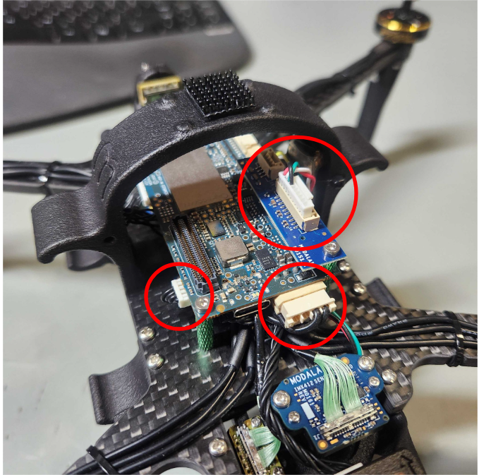
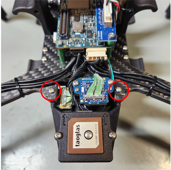
Easiest way to get to the ESC would be remove the connectors that are circled in red
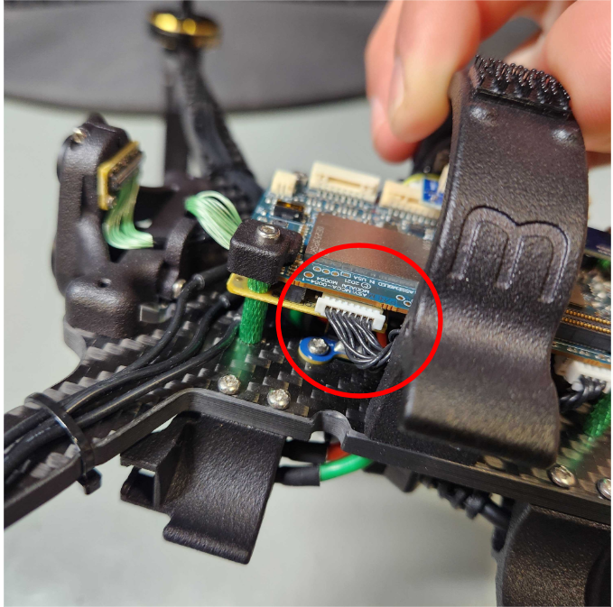
Remove the circled screws [PH1 drive] and cut the zip tie with the arrow pointing towards it
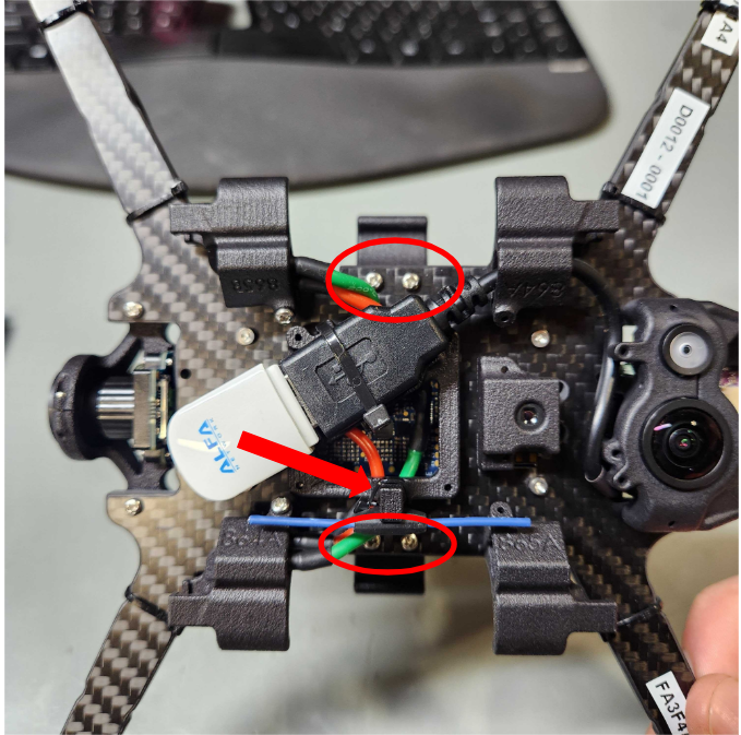
Remove these 2 screws [PH1 drive]
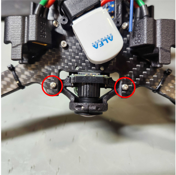
Remove these 2 screws [PH1 drive]
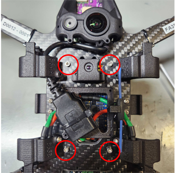
And finally, to get the board stack removed, you'll unscrew these 4 hex screws [1.5mm Hex Drive]
WHEN REMOVING THOSE HEX SCREWS, BE SURE THE CIRCLED STANDOFFS DO NOT ROTATE AT ALL, THIS COULD CAUSE THE SCREWS COMING FROM THE OTHER SIDE OF THE STANDOFF TO GET LOOSE
Keep these by rotating by carefully holding them in place with needle nose pliers or something similar
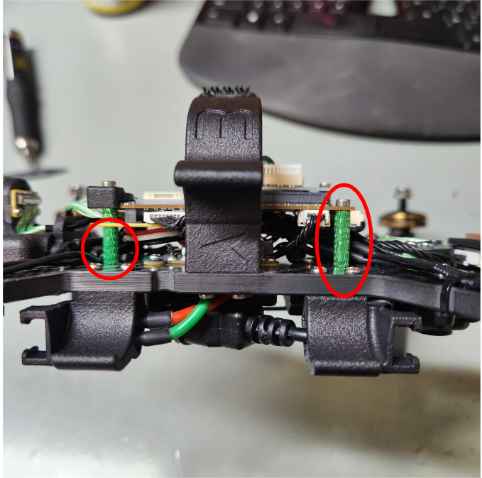
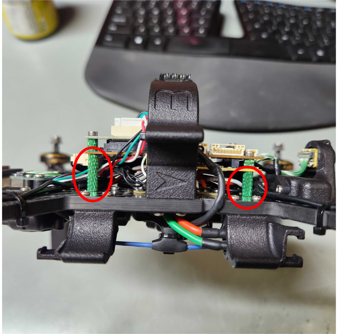
When re-assembling, just make sure all screws going into those standoffs are nice and snug (coming from both the top side and bottom side)
-
Easiest way to get to the ESC would be remove the connectors that are circled in red
Remove the circled screws [PH1 drive] and cut the zip tie with the arrow pointing towards it
Remove these 2 screws [PH1 drive]
Remove these 2 screws [PH1 drive]
And finally, to get the board stack removed, you'll unscrew these 4 hex screws [1.5mm Hex Drive]
WHEN REMOVING THOSE HEX SCREWS, BE SURE THE CIRCLED STANDOFFS DO NOT ROTATE AT ALL, THIS COULD CAUSE THE SCREWS COMING FROM THE OTHER SIDE OF THE STANDOFF TO GET LOOSE
Keep these by rotating by carefully holding them in place with needle nose pliers or something similar
When re-assembling, just make sure all screws going into those standoffs are nice and snug (coming from both the top side and bottom side)
@Dobry-Kolacz thanks for the detailed instructions

-
@griffin
To extend the wires, you only need to solder splice the correct length of extra wire.I'm looking into our custom version being available to you. Probably won't have an answer until the morning
@Jeremy-Schmidt any update on being able to get the custom version? Thanks.
-
@Jeremy-Schmidt any update on being able to get the custom version? Thanks.
@griffin Were you able to get your motors replaced? It sounds like you had ordered the proper spec replacement motors
-
@griffin Were you able to get your motors replaced? It sounds like you had ordered the proper spec replacement motors
@Dobry-Kolacz I ran into some delays due to missing parts/tools. Now I have encountered some difficulties getting the motors desoldered; even with significant flux I cannot get the motor wires to desolder from the ESC with a 650F iron held for 5-10s. The solder does not seem to heat up and become liquid.
Do you have any tips or advice for this step?
Kind regards,
Griffin -
@griffin Were you able to get your motors replaced? It sounds like you had ordered the proper spec replacement motors
@Dobry-Kolacz I've tried some continued effort and still can't get the wires to budge. I am worried that there is a heatsink mounted to the ESC soaking up the heat from the soldering iron but I don't want to just hold the iron to the board for too long to prevent damaging it.
What is the ModalAI-approved technique for replacing motor wires?
thanks,
Griffin -
@Dobry-Kolacz I've tried some continued effort and still can't get the wires to budge. I am worried that there is a heatsink mounted to the ESC soaking up the heat from the soldering iron but I don't want to just hold the iron to the board for too long to prevent damaging it.
What is the ModalAI-approved technique for replacing motor wires?
thanks,
Griffin@griffin Sorry for the delay in response.
We use lead free solder so it is very important that a sufficient amount of flux is used during both the soldering and de-soldering process
Typical procedure for us would look something like putting some flux on the solder joint. We use Chip Quik SMD291 which can reliably be found on mouser.com or digikey.com Amazon might have it too.
It is very important that the soldering tip you are working with is clean and able to easily hold solder on any part of the working area you apply solder to (it shouldn't just bead up on one part of the tip and avoid the rest of the tip area). 650F should be plenty hot for the small solder pads on that ESC
With a clean tip, you can apply a small amount of solder to the tip (this will help thermal transfer and solder liquidation to happen faster)
Then place the slightly wetted side of the soldering tip to the pad. The flux will make it a bit smokey on first contact but the joint should fairly quickly liquidate and allow you to remove the wireHope that helps!
-
@griffin Sorry for the delay in response.
We use lead free solder so it is very important that a sufficient amount of flux is used during both the soldering and de-soldering process
Typical procedure for us would look something like putting some flux on the solder joint. We use Chip Quik SMD291 which can reliably be found on mouser.com or digikey.com Amazon might have it too.
It is very important that the soldering tip you are working with is clean and able to easily hold solder on any part of the working area you apply solder to (it shouldn't just bead up on one part of the tip and avoid the rest of the tip area). 650F should be plenty hot for the small solder pads on that ESC
With a clean tip, you can apply a small amount of solder to the tip (this will help thermal transfer and solder liquidation to happen faster)
Then place the slightly wetted side of the soldering tip to the pad. The flux will make it a bit smokey on first contact but the joint should fairly quickly liquidate and allow you to remove the wireHope that helps!
@Dobry-Kolacz Thanks for the advice! After some further effort I ended up simply cutting the existing wires and splicing the new wires to these rather than desoldering from the ESC. The drone is back up and flying after being reassembled.
-
@Dobry-Kolacz Thanks for the advice! After some further effort I ended up simply cutting the existing wires and splicing the new wires to these rather than desoldering from the ESC. The drone is back up and flying after being reassembled.
@griffin Great to hear!!
It is possible, depending on what size tip and what kind of soldering iron you were using, that 650F may actually not have been hot enough. After talking about it with my team I realized that we have set our irons up to the 750-800F range.
Nonetheless, it is likely the safest option to just splice in the new wires just as you have done
-
A Alex Kushleyev referenced this topic on


Reading along? Create a free ModalAI Forum account to join in.
With an account you can reply, ask your own question, get an email when a ModalAI engineer answers, and mark the reply that solved it. Your place in each thread is saved between visits.
Questions about VOXL, Flight Core, ESCs and ModalAI drones are answered here by the engineers who build them.
Register Login