Though I cannot answer your question about sourcing/ordering a motor replacement, I just want to point out that there are two washers placed in between each motor and arm on the drone frame. Each arm has the washers installed in a specific location to aid handling. Observe and take note of the washer position so when you take off and replace the motor, you will be able to properly reinstall the washers
Dobry Kolacz
@Dobry Kolacz
Best posts made by Dobry Kolacz
-
RE: Motor Damagedposted in Ask your questions right here!
-
RE: Calibrating Stereo Cameras on VOXL Flightcore is Super Finickyposted in VOXL Flight
You can also get a different idea of what the camera is seeing by adding a "-t" to the end of the code line. For example: "voxl-calibrate-camera stereo -t "
This makes it easier to gauge if the lighting is good and can provide a different perspective which might make calibration easier. -
RE: px4 disconnected from uartposted in Ask your questions right here!
@Syed-Omair Follow the Red/Black/Yellow cables coming out of the flight core to the receiver
Latest posts made by Dobry Kolacz
-
RE: VOXL Starling 2 Max hires_front camera unresponsiveposted in Support Request Format for Best Results
@brandon Do you have a plastic spudger tool? Something like this. A plastic tool will significantly reduce the possibility of damaging any components (compared to using anything hard like metal). Press only on the metal part of the connector to prevent warping that plastic nub end.
Typically we use a fingernail to press those connectors in place but for that connector in particular it would be hard to reach with a fingernail.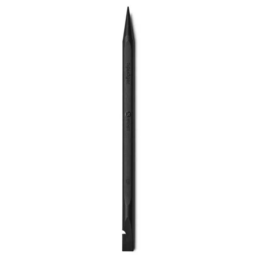
-
RE: VOXL Starling 2 Max hires_front camera unresponsiveposted in Support Request Format for Best Results
@brandon Hmm, they look fairly well plugged in as far as I can tell. I'd say look at it from a side profile and if you see anything sticking out or bulging, you'll know it was a poorly seated connector.
Just for good measure, go ahead and press against the back of those connectors just to be sure they're fully seated in there. From a side profile, everything should look flat/parallel with the board.
-
RE: VOXL Starling 2 Max hires_front camera unresponsiveposted in Support Request Format for Best Results
@brandon Could you please send some photos of what your front camera assembly looks like. I'd like too see all the connections, some views of the camera itself, and what the plastic housing around the cams look like. We verify all cameras are working and get them focused during assembly so I'm trying to track down what could have caused the failure.
-
RE: IMX412 Poor performance vs IMX214?posted in Ask your questions right here!
We focus the lens then apply just a small drop on the outside of the barrel/threads where the lens interfaces with the housing
-
RE: Motor Replacement Instructions Starling 2 Maxposted in Starling & Starling 2
@griffin Great to hear!!
It is possible, depending on what size tip and what kind of soldering iron you were using, that 650F may actually not have been hot enough. After talking about it with my team I realized that we have set our irons up to the 750-800F range.
Nonetheless, it is likely the safest option to just splice in the new wires just as you have done
-
RE: IMX412 Poor performance vs IMX214?posted in Ask your questions right here!
You're welcome!
The epoxy used is UV cure epoxy. Any uncured epoxy should be able to be wiped away with a microfiber as Alex mentioned, using isopropyl alcohol in conjunction does wonders.
We have recently switched to using RTV silicone to secure these lenses in place which seems to be working well for us.
-
RE: Motor Replacement Instructions Starling 2 Maxposted in Starling & Starling 2
@griffin Sorry for the delay in response.
We use lead free solder so it is very important that a sufficient amount of flux is used during both the soldering and de-soldering process
Typical procedure for us would look something like putting some flux on the solder joint. We use Chip Quik SMD291 which can reliably be found on mouser.com or digikey.com Amazon might have it too.
It is very important that the soldering tip you are working with is clean and able to easily hold solder on any part of the working area you apply solder to (it shouldn't just bead up on one part of the tip and avoid the rest of the tip area). 650F should be plenty hot for the small solder pads on that ESC
With a clean tip, you can apply a small amount of solder to the tip (this will help thermal transfer and solder liquidation to happen faster)
Then place the slightly wetted side of the soldering tip to the pad. The flux will make it a bit smokey on first contact but the joint should fairly quickly liquidate and allow you to remove the wireHope that helps!
-
RE: Batteries charging errorposted in Power Modules
That is a concerning failure rate.
In production we use these batteries on a daily basis with no issues. The only time we see failures is when the battery has seen a lot of use and eventually the power leads can break off from their soldered connection to the tabs on the cells. This happens when too much force is applied to the battery power cable typically when unplugging the battery from the drone.
It is imperative that whenever unplugging a battery from anything, all your pulling force must be applied through the XT30 connection. If force is applied anywhere else, there is a risk of damaging the power lead connections to the battery
.
.
.
.
And as a side note/reminder: please do not spin the motors when using the wall power supply, doing so will damage the ESC -
RE: IMX412 Poor performance vs IMX214?posted in Ask your questions right here!
If you cannot get the lens to spin with the epoxy in place, you can take some small tweezers and pick away at the glue. That should eventually free up enough of the threads/barrel to allow for focal adjustment.
Please ping me if you have issues getting the lens loose
-
RE: Motor Replacement Instructions Starling 2 Maxposted in Starling & Starling 2
@griffin Were you able to get your motors replaced? It sounds like you had ordered the proper spec replacement motors