@Eric-Katzfey Dronetag DRI, It expects to accept MAVLink data from the flight controller.
Posts made by Jeremy Frederick
-
RE: External MAVLink Connection using VOXL 2 through ttyHS1
-
RE: VOXL 2 IO Board troubleshooting - Driver will not start
@Vinny Appreciate the heads up
-
RE: External MAVLink Connection using VOXL 2 through ttyHS1
@Zachary-Lowell-0 I'm attempting to communicate through the UART ttyHS1 that is made available on the USB expansion board.
-
External MAVLink Connection using VOXL 2 through ttyHS1
I'm looking to establish an external MAVLink connection to the voxl-px4 service on VOXL 2 through the ttyHS1 of the USB3 expansion board. I'm looking to integrate a third party RemoteID module, and am not implementing an external flight controller.
All the documentation and questions on the forum I could find seem to reference an external flight controller use case, or an internal MAVROS/MAVSDK use case. How do I go about configuring the mavlink-server to output MAVLink on this external UART while maintaining the VOXL 2's PX4 capability.
-
RE: VOXL 2 IO Board troubleshooting - Driver will not start
@valvarez Any PWM based servo should work, we're using 5g servos with very little torque capability and haven't seen any issues with the power supply capabilities of the IO board in this regard. I connected the PWM Signal to output 1 on the IO board and the 5V and G of the same port. Has been working consistently through QGC.
-
FPV ESC PWM Signal Control
Currently using the VOXL IO board for PWM control on the VOXL 2 using SDK 1.3.5, I am beginning to integrate the FPV ESC and noticed that it has listed PWM output capabilities. If I can remove the VOXL IO board from the loop that would be ideal from a SWaP perspective. However, there is little documentation on how to get the PWM control to work through PX4 outside of what is listed in the test script. Has PWM output on the ESCs been fully integrated, separate from the ESC control which we would prefer to keep over the UART. Or, is the VOXL IO board still the only way to integrate PWM control out of the box with the Modal AI ecosystem? PWM control will be used for Payload control specifically.
-
RE: Looking for Help Understanding the GPIO mapping on the QRB5165
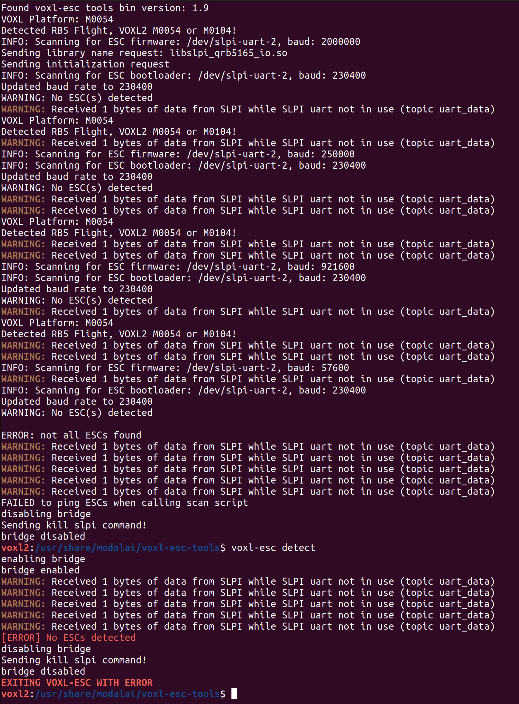
@tom Looks like I just needed to update the ESC firmware to the latest variant, that got the python script to work, still working on PX4 though, I'm using Joystick controls through QGC rather than an RC radio so I cannot Map an RC channel, using the actuator testing panel instead and set GPIO_CTL_CH = 3 and RC AUX 3 to one of the outputs, doesn't seem to be triggering the LED yet but I'm not sure if RC AUX 3 sends the same message as with a RC Controller, going to try going through the VOXL IO functionality instead of the ESC output next. In the end, we'll just be integrating it into our custom QGC fork, however want to test it before going through the effort.
-
RE: Looking for Help Understanding the GPIO mapping on the QRB5165
@tom Seems like neither the voxl-esc-gpio.py test script or the PX4 triggering via RC_AUX seems to be having an effect on the PF0 GPIO on the ESC. Currently, I am using SDK 1.3.5. I did notice that the voxl-esc-gpio.py has the packet = wrap_data(ESC_PACKET_TYPE_GPIO_CMD,req_data) line commented out, is there anything else that I should check? Perhaps a different ESC firmware?
-
RE: Looking for Help Understanding the GPIO mapping on the QRB5165
@Alex-Kushleyev Yeah, even if we can't trigger it through PX4, having to stop voxl-px4 will not work
-
RE: Looking for Help Understanding the GPIO mapping on the QRB5165
@Alex-Kushleyev I'm specifically interested in toggling the VTX on/off GPIO on the ESC as described in the attached image.
-
Looking for Help Understanding the GPIO mapping on the QRB5165
I'm using the FPV ESC and noticed the feature for switching VTX power on/off. I see in the documentation that the pin is labeled as CH0 PF0, and am struggling to figure out which pin in sys/class/gpio this refers too. Some clarity on this would be very helpful.
-
RE: Microhard USB Carrier Board Integration with VOXL 2 (As opposed to the add on board)
@Vinny I've been assessing the FPV ESC with its built in 5V regulator for the VOXL 2 up to 6A. On the bench, I haven't clocked the VOXL 2 drawing any more then 2A, (albeit we're not using many of the CPU heavy services). Do you think this regulator would be capable of powering the VOXL 2 as well as the Microhard modem up to 2A?
-
RE: Microhard USB Carrier Board Integration with VOXL 2 (As opposed to the add on board)
@Vinny Appreciate the option, just now noticing that the USB2 Fast boot board is no longer being sold, I assume its been replaced by the USB3 breakout board. Is this board still capable of providing up to 5A to the peripheral modem as demonstrated in the doodle labs radio integration guide?
-
RE: Microhard USB Carrier Board Integration with VOXL 2 (As opposed to the add on board)
@Jeremy-Frederick Just tried a separate carrier board and modem and it seems to be working just fine now
-
Microhard USB Carrier Board Integration with VOXL 2 (As opposed to the add on board)
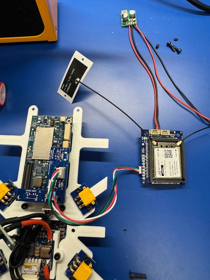
Hello, for form factor reasons, and to get the maximum db output of the microhard module, I want to try and integrate the Microhard USB Carrier Board with the VOXL 2 instead of the standard Add on Board. I'm attempting to set it up identical to how the doodle labs radios integrate, through the USB 2 fastboot board on the VOXL 2. I have been unsuccessful in creating a network connection to the radio.
Is there any reason why this integration wouldn't work? Is there anything that can be done to get this integration to work?
-
RE: Timeline for open-vins documentation
@Viktor-Gal No, not yet, I have the service running but no overlay available.
-
Timeline for open-vins documentation
Hello, I've begun playing around with the new open-vins implementation on VOXL 2 and I was curious when your team expects the documentation to be posted up on the website.
-
RE: Frequent Horizontal Lines in IMX214 Sensor (SKU: MSU-M0024 ).
{
"version": 0.1,
"fsync_en": false,
"fsync_gpio": 109,
"cameras": [{
"type": "ar0144",
"name": "tracking",
"enabled": true,
"camera_id": 0,
"fps": 30,
"en_rotate": false,
"en_preview": true,
"preview_width": 1280,
"preview_height": 800,
"en_raw_preview": true,
"ae_mode": "lme_msv",
"ae_desired_msv": 60,
"exposure_min_us": 20,
"exposure_max_us": 33000,
"gain_min": 54,
"gain_max": 8000,
"exposure_soft_min_us": 5000,
"ae_filter_alpha": 0.600000023841858,
"ae_ignore_fraction": 0.20000000298023224,
"ae_slope": 0.05000000074505806,
"ae_exposure_period": 1,
"ae_gain_period": 1
}, {
"type": "imx214",
"name": "hires",
"enabled": true,
"camera_id": 1,
"fps": 30,
"en_preview": false,
"preview_width": 640,
"preview_height": 480,
"en_raw_preview": false,
"en_small_video": true,
"small_video_width": 1024,
"small_video_height": 768,
"small_venc_mode": "h265",
"small_venc_br_ctrl": "cqp",
"small_venc_Qfixed": 30,
"small_venc_Qmin": 15,
"small_venc_Qmax": 40,
"small_venc_nPframes": 9,
"small_venc_mbps": 2,
"en_large_video": true,
"large_video_width": 4208,
"large_video_height": 3120,
"large_venc_mode": "h265",
"large_venc_br_ctrl": "cqp",
"large_venc_Qfixed": 38,
"large_venc_Qmin": 15,
"large_venc_Qmax": 50,
"large_venc_nPframes": 29,
"large_venc_mbps": 30,
"en_snapshot": true,
"en_snapshot_width": 4208,
"en_snapshot_height": 3120,
"exif_focal_length": 0,
"exif_focal_length_in_35mm_format": 0,
"exif_fnumber": 0,
"ae_mode": "isp"
}]
} -
RE: Frequent Horizontal Lines in IMX214 Sensor (SKU: MSU-M0024 ).
@Alex-Kushleyev We have IMX214 connected to J7 Upper through the m0084 cable. Alongside it is a ARR0144 Tracking Camera connected to J7 Lower.