How to Enable QUP19 and QUP13 as UARTs on VOXL 2 (ttyHS2 / ttyHS3)?
-
Hi everyone
I'm working on a VOXL 2, M0054 , voxl2_SDK_1.4.1
I’ve successfully used /dev/ttyHS1 (QUP7) via J3, but I’m currently trying to enable and use:
/dev/ttyHS2 → QUP19 (GPIO 2 and 3, J5 pins 48 and 49)

/dev/ttyHS3 → QUP13 (GPIO 38 and 39, J5 pins 97 and 98)
These devices show up in /dev, but the corresponding pins remain unclaimed in the pinctrl debug output:
cat /sys/kernel/debug/pinctrl/*/pinmux-pins | grep -E 'GPIO_2|GPIO_3|GPIO_38|GPIO_39'pin 2 (GPIO_2): 894000.qcom,qup_uart (GPIO UNCLAIMED) function qup19 group gpio2 pin 3 (GPIO_3): 894000.qcom,qup_uart (GPIO UNCLAIMED) function qup19 group gpio3 pin 38 (GPIO_38): a94000.qcom,qup_uart (GPIO UNCLAIMED) function qup13 group gpio38 pin 39 (GPIO_39): a94000.qcom,qup_uart (GPIO UNCLAIMED) function qup13 group gpio39How can I claim it to UART?
Many Thanks!
@yardy ,
Since the devices appear in
/dev/ttyHS*, it means they are already mapped and pins are claimed by the kernel, so it's all set up. You will just need to use the correct adapter board that plugs into VOXL2 and exposes these uart connections.The GPIO mapping is not relevant here because the pins are not used as GPIO (different kernel driver (uart) ).
Alex
-
@yardy ,
Since the devices appear in
/dev/ttyHS*, it means they are already mapped and pins are claimed by the kernel, so it's all set up. You will just need to use the correct adapter board that plugs into VOXL2 and exposes these uart connections.The GPIO mapping is not relevant here because the pins are not used as GPIO (different kernel driver (uart) ).
Alex
thanks for replying.
I'm using the dev test board but couldn't establish the commany ideas?
B.R
-
thanks for replying.
I'm using the dev test board but couldn't establish the commany ideas?
B.R
@yardy , can you please clarify how exactly you are testing the communication using HS2 and HS3?
-
@yardy , can you please clarify how exactly you are testing the communication using HS2 and HS3?
@Alex-Kushleyev , Thanks for the response!
VOXL 2 mounted on the VOXL 2 Developer Test Board.
CP2102 USB-to-UART dongle connected to my PC.
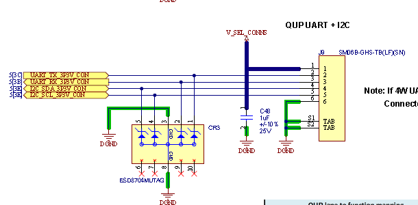
For QUP19 (ttyHS2):GPIO_2 (TX) connected to RX on CP2102 via JP1 (for level shifter) and J9
GPIO_3 (RX) connected to TX on CP2102 via JP1 (for level shifter) and J9
GND to GNDon the voxl2:
stty -F /dev/ttyHS2 115200
cat /dev/ttyHS2
echo "Hello from VOXL2 HS2" > /dev/ttyHS2on my PC:
OS: Ubuntu 22.04screen /dev/ttyUSB0 115200When I send text from the PC side, I expect it to appear in the cat output on VOXL2, and vice versa.
with /dev/ttyHS1 it works.
-
@Alex-Kushleyev , Thanks for the response!
VOXL 2 mounted on the VOXL 2 Developer Test Board.
CP2102 USB-to-UART dongle connected to my PC.
For QUP19 (ttyHS2):GPIO_2 (TX) connected to RX on CP2102 via JP1 (for level shifter) and J9
GPIO_3 (RX) connected to TX on CP2102 via JP1 (for level shifter) and J9
GND to GNDon the voxl2:
stty -F /dev/ttyHS2 115200
cat /dev/ttyHS2
echo "Hello from VOXL2 HS2" > /dev/ttyHS2on my PC:
OS: Ubuntu 22.04screen /dev/ttyUSB0 115200When I send text from the PC side, I expect it to appear in the cat output on VOXL2, and vice versa.
with /dev/ttyHS1 it works.
-
Hi @yardy
Are you using the jumper blocks J14.15/J14.17 to JP1.10/JP1.12 respectively for QUP_19?
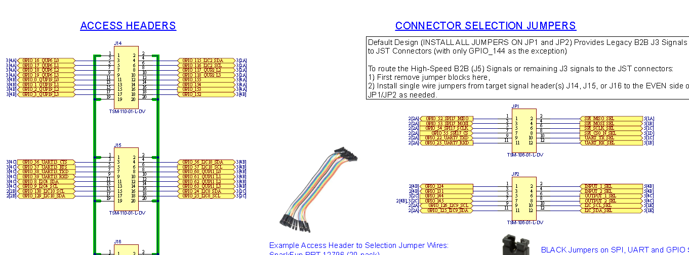
That will result in 3.3V RX/TX signals at J9 on M0144.
Just want to clarify so that SW is not chasing any red herrings.
Thanks! -
@yardy ,
Can you please try the following:
- install
screenon voxl2 by runningapt install screen, then you can use the tool to simplify your testing. - bridge the RX and TX for a particular UART that you are testing (on the Developer Test Board) and run a simple test such as :
screen /dev/ttyHS2 115200When you type into the terminal while running screen, if the communication is working, you should see the characters that you type being printed in the terminal.
If you still do not see any chars in this test, please use an oscilloscope to probe the UART TX line at the test board (while TX is not connected to the RX) and see if you see any data on the waveform when you type in the terminal on the voxl2 side while
screenis running.Alex
- install
-
@yardy ,
Can you please try the following:
- install
screenon voxl2 by runningapt install screen, then you can use the tool to simplify your testing. - bridge the RX and TX for a particular UART that you are testing (on the Developer Test Board) and run a simple test such as :
screen /dev/ttyHS2 115200When you type into the terminal while running screen, if the communication is working, you should see the characters that you type being printed in the terminal.
If you still do not see any chars in this test, please use an oscilloscope to probe the UART TX line at the test board (while TX is not connected to the RX) and see if you see any data on the waveform when you type in the terminal on the voxl2 side while
screenis running.Alex
Hi @yardy Are you using the jumper blocks J14.15/J14.17 to JP1.10/JP1.12 respectively for QUP_19?It was connected to JP1.9/JP1.11 (because of the jumpers... I was wrong)
It's working!
Many thanks

- install
Hello! It looks like you're interested in this conversation, but you don't have an account yet.
Getting fed up of having to scroll through the same posts each visit? When you register for an account, you'll always come back to exactly where you were before, and choose to be notified of new replies (either via email, or push notification). You'll also be able to save bookmarks and upvote posts to show your appreciation to other community members.
With your input, this post could be even better 💗
Register Login