VOXL2 IO expander power
-
Hello,
My VOXL2 is not outputting 3.3v to the IO expander. Is there something I have to configure to enable power to these pins?
I have it plugged into the last 4 pins of J19 and nothing lights up. Even without it plugged in, I measured the voltage across pins 9 and 12, and it's just a few mV.Thanks,
Patrick -
Hi @Patrick-Hinchey ,
That pin (should be) set high by default in the standard kernel, it takes a few seconds after bootup to enable, but I'm sure you've measured after that.
Are you using the standard kernel? If it's not high, I'm wondering about a regulator that is controlled via GPIO159:
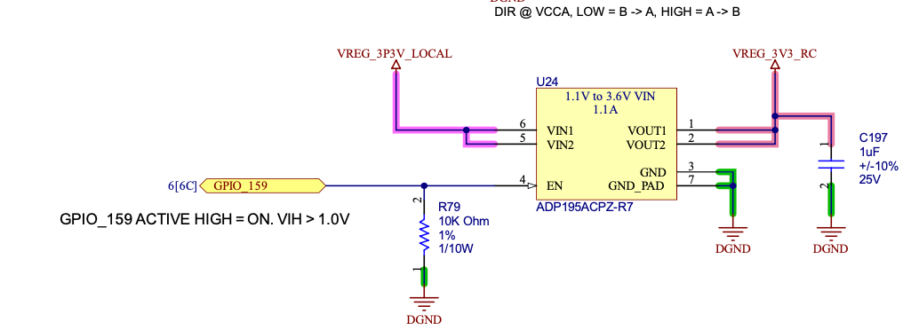
For reference, here's where it's set in the kernel:
https://gitlab.com/voxl-public/system-image-build/qrb5165-kernel/-/blob/dev/arch/arm64/boot/dts/vendor/qcom/m0054-modalai-gpio.dtsi#L12 -
Hi @Patrick-Hinchey , Can you confirm if you see +3.3V on J10 pin 1 with Pin 8 as GND?
This is just a simple sanity test of the "VREG_3P3V_LOCAL" which creates the "VREG_3V3_RC". If so, then please follow Travis' notes about maybe some software is now overriding the default settings.
If not, please ping on me again and I can help narrow down what HW issue you may have.
Thanks! -
Hi Vinny, thanks for the quick reply.
The voltage across J10 pins 1 & 8 is close to 0 as well -
Hi Vinny, thanks for the quick reply.
The voltage across J10 pins 1 & 8 is close to 0 as well@Patrick-Hinchey Hi,
is your board otherwise working? Can you ADB into it, run basic stuff like on this tutorial page: https://docs.modalai.com/voxl2-setup-adb/Is LED "D1" on Green?
It's the one located here at the bottom of the PCB, left of the mounting hole:
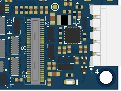
If it is not ON and you cannot run even basic ADB commands following our tutorial, then it sounds like your hardware is busted.
However, if indeed that LED is ON Green, then that tells me a few things:- Your DMM (or scope) might be set for AC mode
- Your DMM (or scope) is not functioning.
Basically, that green LED is a "power good" indicator which includes the 3.3V rail you are probing.
Is it also possible you might have other cables installed that are incorrectly shorting 3.3V to GND?
Can you repeat the measurements with only USB-C and the power cable plugged in (no cameras, no ESC, etc).Let us know!
-
@Patrick-Hinchey Hi,
is your board otherwise working? Can you ADB into it, run basic stuff like on this tutorial page: https://docs.modalai.com/voxl2-setup-adb/Is LED "D1" on Green?
It's the one located here at the bottom of the PCB, left of the mounting hole:
If it is not ON and you cannot run even basic ADB commands following our tutorial, then it sounds like your hardware is busted.
However, if indeed that LED is ON Green, then that tells me a few things:- Your DMM (or scope) might be set for AC mode
- Your DMM (or scope) is not functioning.
Basically, that green LED is a "power good" indicator which includes the 3.3V rail you are probing.
Is it also possible you might have other cables installed that are incorrectly shorting 3.3V to GND?
Can you repeat the measurements with only USB-C and the power cable plugged in (no cameras, no ESC, etc).Let us know!
@Vinny D1 is not illuminated, but the LED on the other side, right under the USB-C connector is illuminated. I can connect with adb and browse the file system, run commands etc.
I tried with another board and D1 is lit, and the RC receiver is now receiving power. Looks like it was a busted 3.3v regulator.
I have a SMD rework station - I'm happy to try replacing the regulator if you tell me where it is
-
@Vinny D1 is not illuminated, but the LED on the other side, right under the USB-C connector is illuminated. I can connect with adb and browse the file system, run commands etc.
I tried with another board and D1 is lit, and the RC receiver is now receiving power. Looks like it was a busted 3.3v regulator.
I have a SMD rework station - I'm happy to try replacing the regulator if you tell me where it is
@Patrick-Hinchey oh wow, ok you're the first to have a damaged 3.3v regulator in several thousand boards. How new is your pcb? The rework is too difficult for anyone to do with hand soldering, it requires heat trays and hot air nozzles. We are best to issue you an RMA (this also let's us look at it to see why it broke).
I'll have to pull in @modalab to help but I think we have an RMA form online you can fill out and if we find the issue is on our end we'll replace or issue you credit for a replacement unit. -
Hey @Patrick-Hinchey would you please send that board in for an RMA diagnostic. Details on our RMA process are here
Before shipping the unit, please purchase an RMA via the link above and fill out the RMA form here. If you have any questions please let me know.
Thank you!
Hello! It looks like you're interested in this conversation, but you don't have an account yet.
Getting fed up of having to scroll through the same posts each visit? When you register for an account, you'll always come back to exactly where you were before, and choose to be notified of new replies (either via email, or push notification). You'll also be able to save bookmarks and upvote posts to show your appreciation to other community members.
With your input, this post could be even better 💗
Register Login