
Questions Regarding the Camera M0161 Design
-
Hardware:
Camera M0161 and cable MCBL-00084
What I am trying to do:
Camera M0161 PCB Design
What actually happens:
The datasheet is incomplete, and we have some questions that need clarification and confirmation:
1:I couldn't find a detailed datasheet for the camera cable MCBL-00084, so I'm not sure about the pin-to-pin mapping between the two ends of the cable. Also, does this cable have a 100 Ω differential impedance and 50 Ω single-ended impedance?2:I am using Hirose DF56C-26S-0.3V(51) 26-pin micro-coax receptacle to connect with camera and cable. however I'm not sure about the signal pin order.Is that correct? Signals are listed in J2 on M0155 https://docs.modalai.com/M0155/
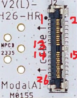
3:what is the purpose of pin 25 on the M0161, labeled "3.8V Primary 'Phone' Power (mimics nominal 1S)"?
Can I use 3.3v to this pin, or can I leave it unconnected?
Reading along? Create a free ModalAI Forum account to join in.
With an account you can reply, ask your own question, get an email when a ModalAI engineer answers, and mark the reply that solved it. Your place in each thread is saved between visits.
Questions about VOXL, Flight Core, ESCs and ModalAI drones are answered here by the engineers who build them.
Register Login