
ESC Aux Power Output
-
The technical docs for the 4-in-1 ESCs mention an Aux Power Output of "1x5.0V (adjustable) 500mA" for the M0134 ESC.
What is the pin out for this? I assume it is the AUX IO pads from the data sheet on the bottom side of the PCB. I am unable to locate the what the pin out for these to groups of 4 pads in the technical doc.
-
The technical docs for the 4-in-1 ESCs mention an Aux Power Output of "1x5.0V (adjustable) 500mA" for the M0134 ESC.
What is the pin out for this? I assume it is the AUX IO pads from the data sheet on the bottom side of the PCB. I am unable to locate the what the pin out for these to groups of 4 pads in the technical doc.
@swickliff , sorry about that, we will update the diagram shortly.
Here is the answer to your question.
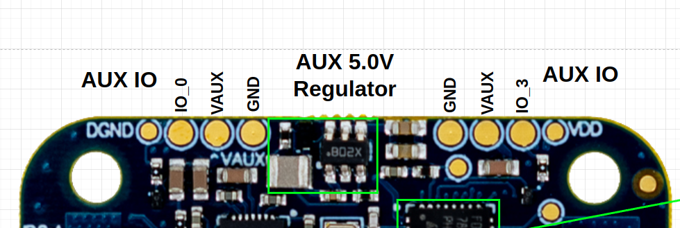
The small test point (top right corner) labeled VDD is the 3.3V that is used by MCUs, it is not recommended to use it for powering external devices, as this can affect ESC performance if the external device affects the MCU power.
both VAUX outputs are tied together and are fed from a single regulator that is set to 5V, rated for 500mA maximum.
The IO_0 and IO_3 pins are currently used for optionally driving neopixel-style led strip, but normally the pins are off (output low state).
I will update the diagram in our docs (here)
-
@swickliff , sorry about that, we will update the diagram shortly.
Here is the answer to your question.
The small test point (top right corner) labeled VDD is the 3.3V that is used by MCUs, it is not recommended to use it for powering external devices, as this can affect ESC performance if the external device affects the MCU power.
both VAUX outputs are tied together and are fed from a single regulator that is set to 5V, rated for 500mA maximum.
The IO_0 and IO_3 pins are currently used for optionally driving neopixel-style led strip, but normally the pins are off (output low state).
I will update the diagram in our docs (here)
One more note.. when soldering to these test points, please use thin and flexible wire and a fine tip of the soldering iron. After soldering, avoid bending the wires, as they could break off the test points if pulled up. if you need to bend the wire after soldering, put your finger right on top of the soldering joint and then bend the wire (this will prevent any movement / lifting of the test point due to wire bending action). After soldering, you can apply some (semi-flexible) glue to fix the wires to the PCB for stress relief.
-
One more note.. when soldering to these test points, please use thin and flexible wire and a fine tip of the soldering iron. After soldering, avoid bending the wires, as they could break off the test points if pulled up. if you need to bend the wire after soldering, put your finger right on top of the soldering joint and then bend the wire (this will prevent any movement / lifting of the test point due to wire bending action). After soldering, you can apply some (semi-flexible) glue to fix the wires to the PCB for stress relief.
@Alex-Kushleyev Thanks for all the info! I'll keep those things in mind when soldering to the pads.
Reading along? Create a free ModalAI Forum account to join in.
With an account you can reply, ask your own question, get an email when a ModalAI engineer answers, and mark the reply that solved it. Your place in each thread is saved between visits.
Questions about VOXL, Flight Core, ESCs and ModalAI drones are answered here by the engineers who build them.
Register Login