Fact Checking my Understanding of the Extrinsic Configuration
-
Hello,
Setup: VOXL 2, SDK 1.4.1, Open-VINs Dual-ARR0144 Cameras
One of my setups will require the VOXL 2 to be mounted upside down, with the MIPI connectors for the cameras facing upwards. I've been preparing the extrinsic file for the setup and wanted confirmation on my understanding of how to properly configure the upside down configuration.
My understanding is such: You must configure PX4 to know the flight controller is upside down, simple enough, with this done, I then go into the extrinsic file and begin setting the rotation and positions offsets.
My question is this: For the "parent": "body",
"child": "imu1",do you set a rotational value of 180 degrees to let the system know the imu is upside down? Then, do you set the camera rotational values to also include the rotation in the board.
For example, the default extrinsic for a forward facing camera and right side up VOXL 2 are:
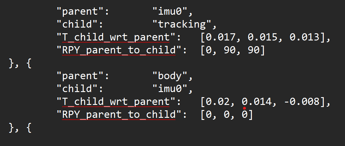
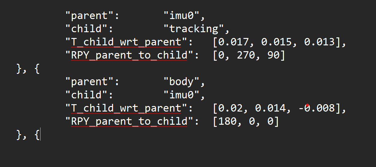
If the VOXL 2 were upside down, would the extrinsics be:
-
@Jeremy-Frederick , just to clarify, there are two IMUs on VOXL2 - one is connected to the DSP, used by PX4 and the second IMU is connected to the Application Processor (CPU). The data flow from the two IMUs normally does not cross, that is to say, that PX4 IMU is used by PX4 and the "apps proc" IMU is used for things like VIO, etc.
PX4 does not use the
extrinsics.conffile, since PX4 has its own configuration for IMU rotation, I believe you know that.Now, regarding the second IMU, if you flip your voxl2 board upside down (lets say roll it 180 degrees around its X axis), then your body->imu0 transform should reflect that [180, 0, 0].
When you specify the transforms between the imu and the cameras, you need to do that in the IMU frame. Perhaps that would be easier if you flip the drone upside down so that the voxl2 is oriented in its nominal orientation and then compute the transforms to the cameras by following the rotations described in our docs (see link below)
The Transform Tree typically looks like this;
       Body
        |
       IMU
        |
------------------
|       |        |
cam0   cam1   cam2
If your tracking camera is initially in forward facing orientation while voxl2 is "right side up", then you have the [0, 90, 90] rotation wrt the imu. if you roll the voxl2 board 180 degrees around its x axis (x axis still points forward), but the camera remains in the same orientation, then your imu->camera transform becomes [180, 90, 90]. You could verify this by using the red-green-blue marker helper tool as shown in the video
")
One way to understand this a bit better, and to do a sanity check.. When rotations are composed, they can be multiplied together as Rotation Matrices. When you compute the rotation between the drone's "body" to the tracking camera, this will look like
body_R_cam = body_R_imu * imu_R_cam. which would be in the default case equal to something like thisbody_R_cam = [Ry(90) * Rz(90)]becausebody_R_imuis Identity Matrix (no rotation).For the use case where VOXL2 is rotated upside down around the x axis, both the
body_R_imuandimu_R_camtransforms have changed but they changed in the same (opposite) way and it just so happens that 180 degree rotation is the same as -180 rotation. So now we havebody_R_cam = [Rx(180)] * [Rx(-180) * Ry(90) * Rz(90)]where the firstRx(180)is thebody_R_imuandRx(-180)is the part of the newimu_R_camtransform. As a result the 180 and -180 degree rotations cancel out and you end up with the originalbody_R_cambecause you have not actually rotated the camera w.r.t to body.. Long explanation but worth the sanity checking.Also more details here : https://docs.modalai.com/configure-extrinsics/
Now, regarding Open Vins actually using the upside down IMU to body rotation correctly, I will need to double check with my colleages. @Cliff-Wong , can you confirm?
-
@Alex-Kushleyev @Cliff-Wong
Subject: QVIO Trajectory Visualization Issue with 180-Degree Roll Rotation on VOXL2Hi,
I'm encountering an issue with QVIO on a VOXL2 setup where the board is rotated 180 degrees around the roll axis. The drone flies well, and the VIO performance is acceptable, but the QVIO trajectory visualization (qvio and Vvhub_body_wrt) does not align with the actual drone movement.Problem Description:
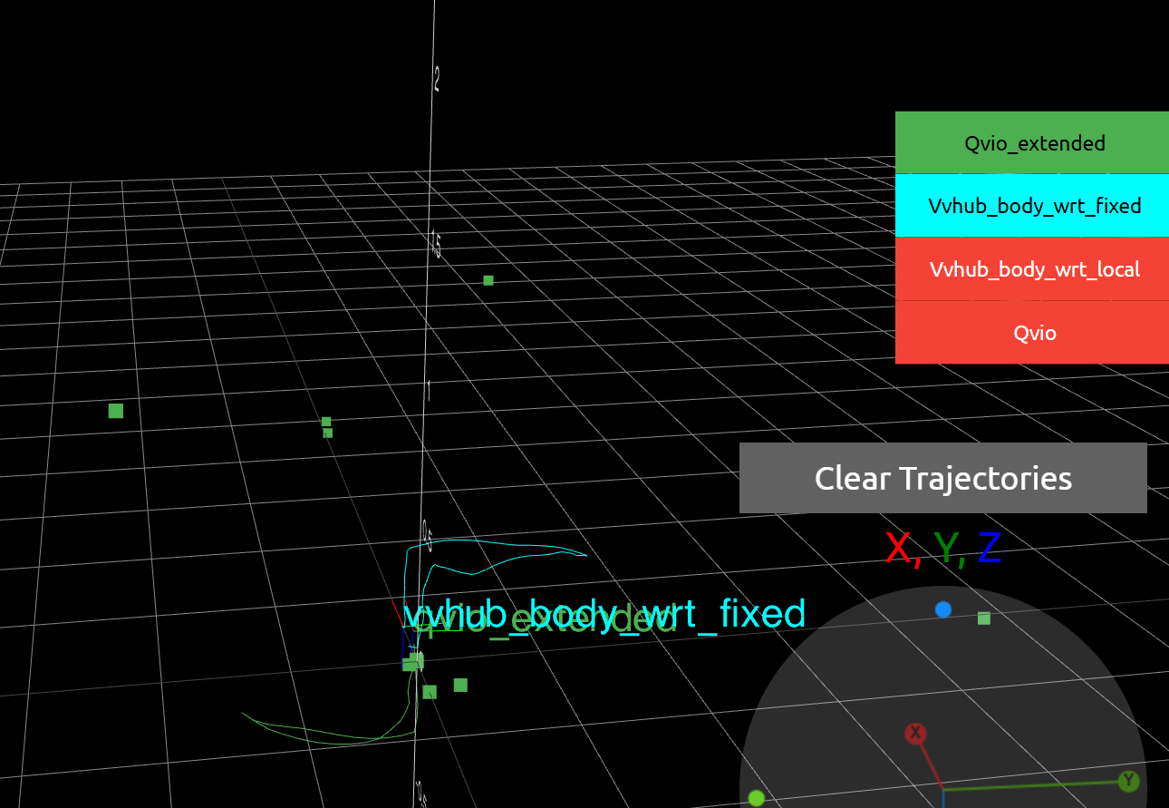
I moved the drone up and to the right, then returned it to its starting position. However, the QVIO visualization shows the movement rotated 180 degrees about the X-axis compared to the actual motion. Please see the attached image for reference:
Extrinsics Configuration:
Here is my current extrinsics configuration:"extrinsics": [{ "parent": "imu_apps", "child": "tracking", "T_child_wrt_parent": [0.05, 0.0067, -0.03], "RPY_parent_to_child": [0, 135, -90] }, { "parent": "body", "child": "imu_apps", "T_child_wrt_parent": [0.025, 0.0067, -0.000360], "RPY_parent_to_child": [180, 0, 0] }, { "parent": "body", "child": "stereo_front_l", "T_child_wrt_parent": [0.0793, -0.040, -0.0243], "RPY_parent_to_child": [0, 90, 90] }, { "parent": "body", "child": "stereo_rear_l", "T_child_wrt_parent": [-0.0297, 0.04, 0.0415], "RPY_parent_to_child": [0, -90, -90] }, { "parent": "body", "child": "tof", "T_child_wrt_parent": [0.078, 0, -0.025], "RPY_parent_to_child": [0, 90, 90] }, { "parent": "body", "child": "ground", "T_child_wrt_parent": [0, 0, 0.058], "RPY_parent_to_child": [0, 0, 0] }]Additional Notes:
I tested an alternative RPY_parent_to_child for the imu_apps to tracking transformation, changing [0, 135, -90] to [180, 45, 90]. Both configurations produce the same results, suggesting they may be equivalent.
The issue persists despite the correct flight behavior, indicating a possible mismatch in the coordinate frame or visualization pipeline.
My version is:-------------------------------------------------------------------------------- system-image: 1.7.10-M0054-14.1a-perf kernel: #1 SMP PREEMPT Fri Sep 27 21:18:59 UTC 2024 4.19.125 -------------------------------------------------------------------------------- hw platform: M0054 mach.var: 1.0.0 -------------------------------------------------------------------------------- voxl-suite: 1.3.5 -------------------------------------------------------------------------------- ... voxl-portal 0.7.0 voxl-qvio-server 1.0.4 voxl-streamer 0.7.4 voxl-suite 1.3.5 voxl-vision-hub 1.8.9 voxl2-system-image 1.7.10-r0Questions:
Could the 180-degree roll rotation of the VOXL2 be causing this visualization discrepancy?
Are there specific calibration steps or configuration adjustments for QVIO to account for this rotation?
Any suggestions for debugging the QVIO trajectory visualization?
Any insights or recommendations would be greatly appreciated. Thank you! -
Updated the SDK to v1.5.0 the problem is still here ¯\(ツ)/¯