New TOF Sensor module Adapter PCB
-
Hello,
I'm planning to upgrade the TOF sensors on my Starling2 Drone with the new TOF along with the new tracking camera as well.
In the new TOF sensor, there are 2 types of flex PCBs which are majorly present. I see that one of the PCBs -
M0169has an additional exclusive 5V DC input from the mainline. Whereas inM0171I see that there are no connectors meant for separate 5V given but only terminal leads given without any exclusive connector.I understand that M0169 board along with the new TOF Sensor was under development and was released beta even before
M0173breakout board. Also what is the significant difference betweenM0169andM0171? Why is external power option not considered exclusively inM0171? What is the advantage of usingM0171overM0169?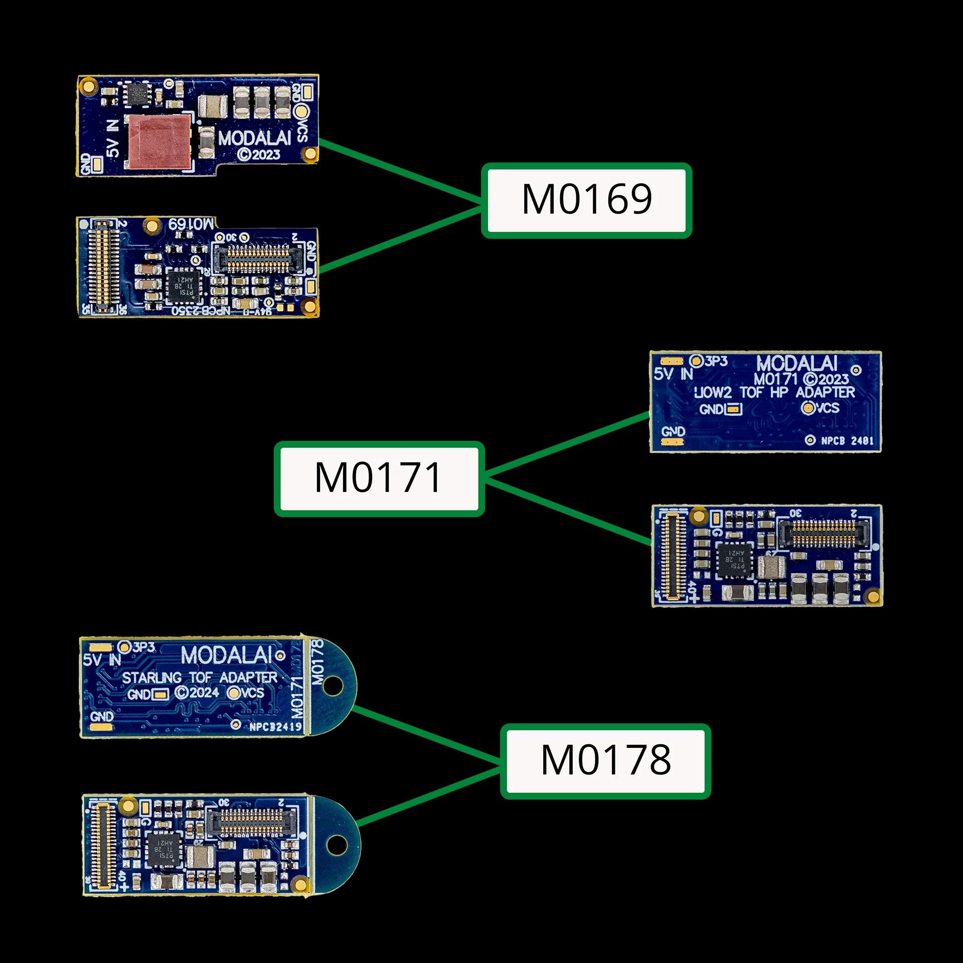
-
Hello,
I'm planning to upgrade the TOF sensors on my Starling2 Drone with the new TOF along with the new tracking camera as well.
In the new TOF sensor, there are 2 types of flex PCBs which are majorly present. I see that one of the PCBs -
M0169has an additional exclusive 5V DC input from the mainline. Whereas inM0171I see that there are no connectors meant for separate 5V given but only terminal leads given without any exclusive connector.I understand that M0169 board along with the new TOF Sensor was under development and was released beta even before
M0173breakout board. Also what is the significant difference betweenM0169andM0171? Why is external power option not considered exclusively inM0171? What is the advantage of usingM0171overM0169?Even here, @Alex-Kushleyev mentions about the usage of external power in
M0169design. -
Even here, @Alex-Kushleyev mentions about the usage of external power in
M0169design.Please take a look at the following links:
https://docs.modalai.com/M0169/
https://docs.modalai.com/M0178/#requirements
https://docs.modalai.com/voxl2-coax-camera-bundles/#mdk-m0173-1-01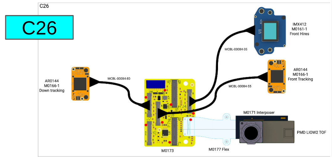
M0169 was built to support the new TOF sensor using the existing (at that time) flex cables and interposers, but those were not designed to carry 5V from VOXL2, therefore M0169 requires additional connector to supply 5V (which can be taken from the same APM that is supplying 5V to VOXL2). TOF V2 sensor can output much higher IR power compared to TOF V1, and the existing interposers / power rails were not designed for that, so an additional 5V input to M0169 is required.
Now, with M0173 (aka Starling 2 Front End), the front end plugs into VOXL2 and makes use of the available 5V on VOXL2 (which was not possible using older interposers and extension cables). M0171 / M0178 is able to pull 5V directly from VOXL via the Starling 2 Front End.
M0178 is basically an M0171 with a tab for mounting.
In order to use M0178 / M0171, you have to use M0177 flex that is connected to M0173 camera front end (which plugs into VOXL2).
So there is basically two options for connecting TOF V2 to VOXL2:
- VOXL2 -> (M0135 or M0076) -> (M0074 or M0036 extender) - > (M0169 + 5V power) -> TOF V2
- VOXL2 -> M0173 -> M0177 - > (M0171 or M0178) -> TOF V2
I know that is a lot of board numbers, but hopefully that makes sense..
Alex
Hello! It looks like you're interested in this conversation, but you don't have an account yet.
Getting fed up of having to scroll through the same posts each visit? When you register for an account, you'll always come back to exactly where you were before, and choose to be notified of new replies (either via email, or push notification). You'll also be able to save bookmarks and upvote posts to show your appreciation to other community members.
With your input, this post could be even better 💗
Register Login