Schematic Review
-
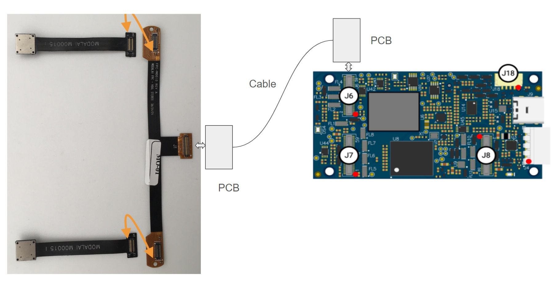
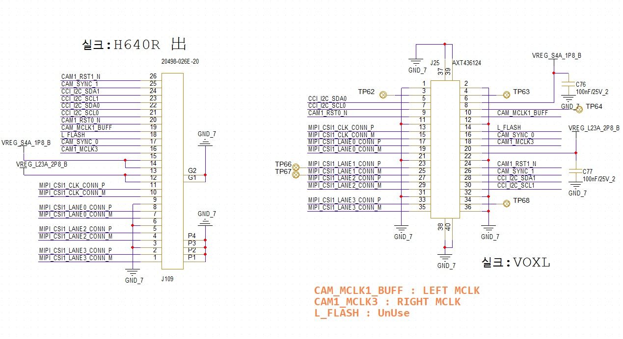
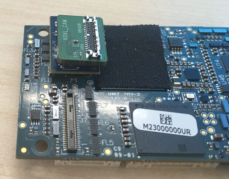
I would like to make sub board like attached picture because out system is too small and cannot install interposer board (M0076). Would you tell me how to connect each signal? (In schematic J1<->J4)
-
I would like to make sub board like attached picture because out system is too small and cannot install interposer board (M0076). Would you tell me how to connect each signal? (In schematic J1<->J4)
Hi @andrea_seock
Sure, I will help you here:
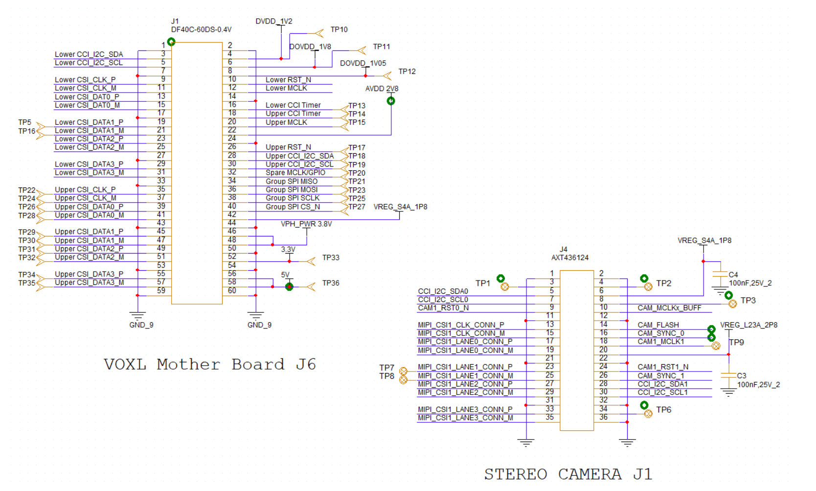
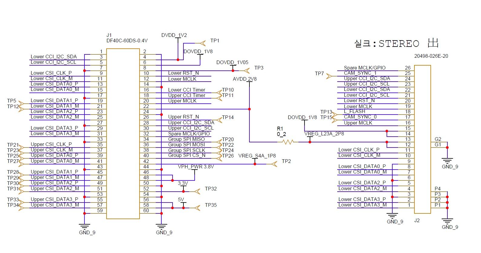
You have some concepts correct, but this is not a correct schematic as I see it with several simple things to fix:- J1 part number is correct
- J4 part number is incorrect. M0076 uses an AXT336124, not the AXT436124 (M0010 use the AXT436124)
- If you are aiming for "smallest", remove the test points from J1 and J4 for unused signals, like the UPPER CSI and unused voltages/signals
")
- DO NOT place test-points on functional CSI lines (TP5/TP16, TP7, TP8 need to be removed). You will break the interface from any stubs.
- Pin 8 on J1 is not a DOVDD, but a DVDD but in this case it is not used.
- The GND connections on J1 (GND_9) do not match the GND connections on J4 (no label shown)
- The net names on J1 and J4 do not match at all. This would need to be fixed for me to review further.
- We recommend to use the DOVDD_1P8V for pin 6 on J4 instead of VREG_S4A_1P8
- Make sure to match Pin 1's in your CAD Symbols as we indicate in our tech docs user guides (and in silk directly) so that your PCB symbols are a drop-in for our products.
Once you have a corrected SCH, please tag me again and I can provide you with another review and once it is correct, I'll provide routing constraints to help make sure you succeed at this design.
Thanks!
Vinny -
Hi @andrea_seock
Sure, I will help you here:
You have some concepts correct, but this is not a correct schematic as I see it with several simple things to fix:- J1 part number is correct
- J4 part number is incorrect. M0076 uses an AXT336124, not the AXT436124 (M0010 use the AXT436124)
- If you are aiming for "smallest", remove the test points from J1 and J4 for unused signals, like the UPPER CSI and unused voltages/signals
- DO NOT place test-points on functional CSI lines (TP5/TP16, TP7, TP8 need to be removed). You will break the interface from any stubs.
- Pin 8 on J1 is not a DOVDD, but a DVDD but in this case it is not used.
- The GND connections on J1 (GND_9) do not match the GND connections on J4 (no label shown)
- The net names on J1 and J4 do not match at all. This would need to be fixed for me to review further.
- We recommend to use the DOVDD_1P8V for pin 6 on J4 instead of VREG_S4A_1P8
- Make sure to match Pin 1's in your CAD Symbols as we indicate in our tech docs user guides (and in silk directly) so that your PCB symbols are a drop-in for our products.
Once you have a corrected SCH, please tag me again and I can provide you with another review and once it is correct, I'll provide routing constraints to help make sure you succeed at this design.
Thanks!
Vinny -
@Vinny Can you check again the schematic?
Hi @andrea_seock
Please help me understand better what you are trying to achieve here.
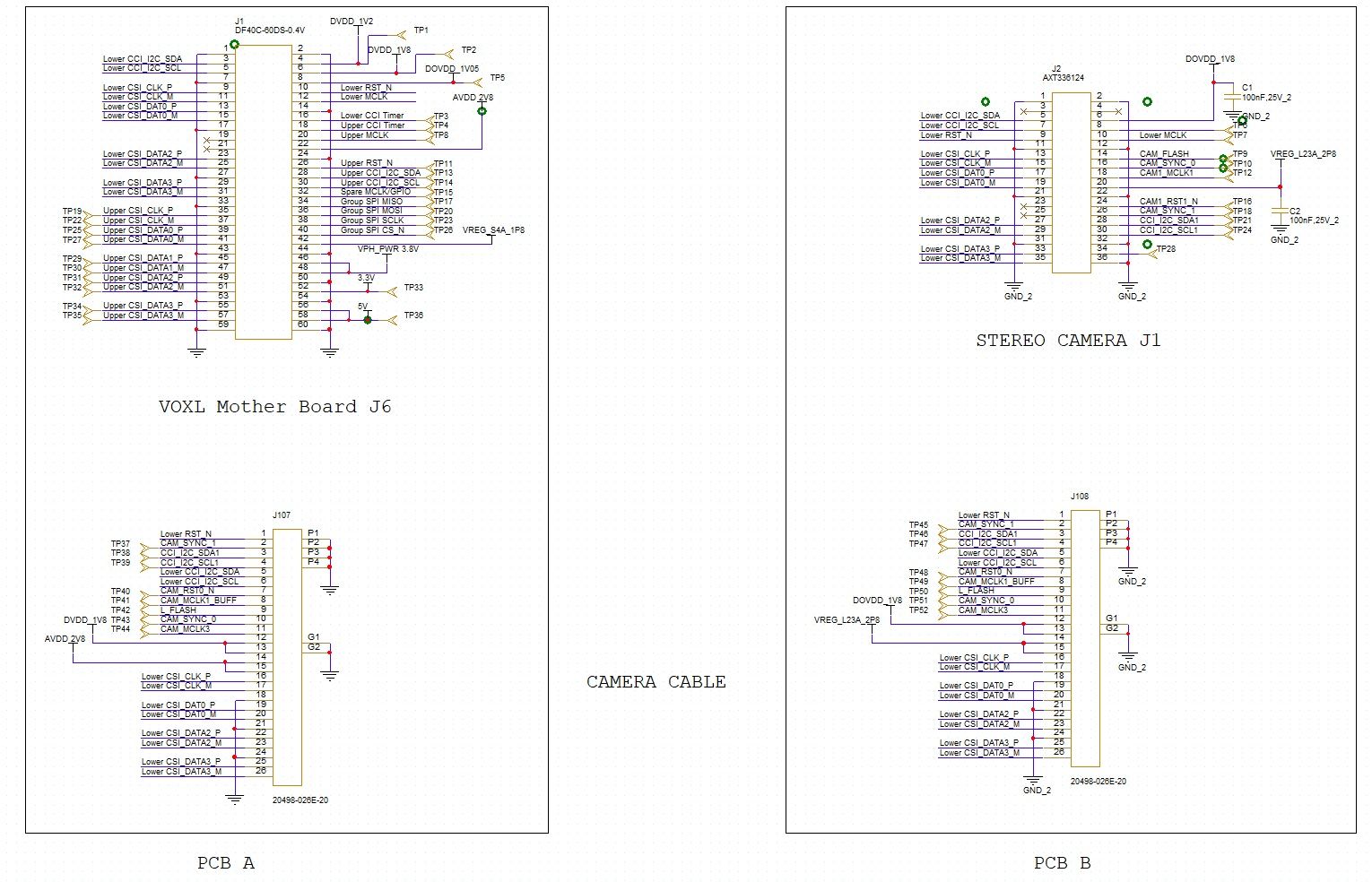
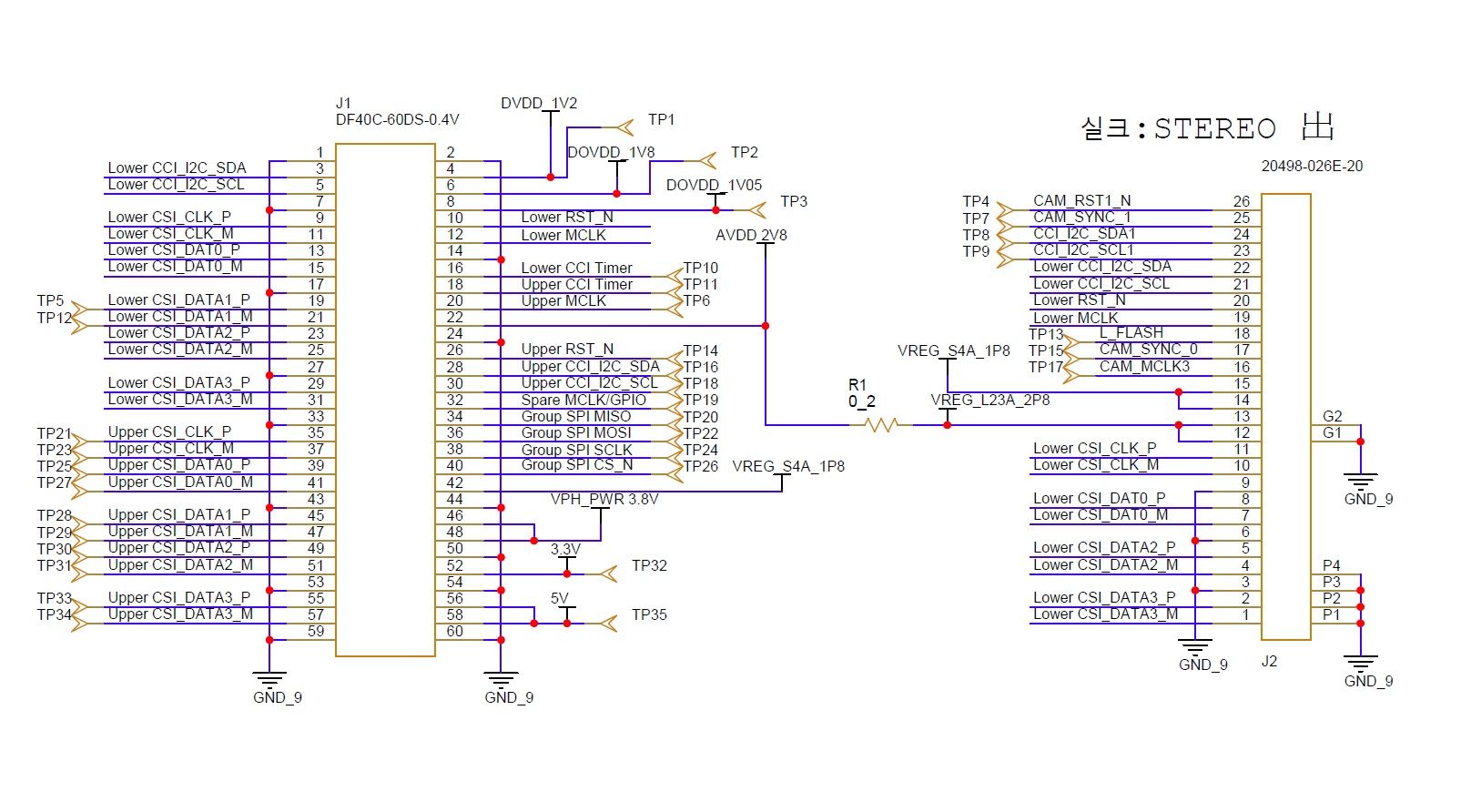
Is this a set of coax adapters?I might be able to interpret this as "J1 <-> J107" and then using a coax cable you go "J107 <-> J108", and then on another PCB you go "J108 <-> J2" Is that correct?
If so, then nicely done. You are close! We have not been perfect in describing the setup needed for Stereo, so I'll try my best to get you corrected:
- Stereo requires 2 unique I2C ports and 2 unique resets. Sometimes MCLK can be shared, but best to have 2.
-
- You need to change "CCI_I2C_SDA1/SCL1" on J107 to match the names on J1 for "UPPER_CCI_I2C_SDA/SCL"
-
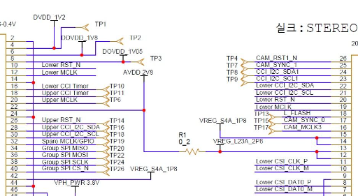
- The CAM1_RST1_N on J2 needs to get over to J1 somehow (your net names are mismatched between J2 and J108). Then, CAM1_RST1_N needs to connect to J1 pin 32 (SPARE_MCLK/GPIO)
-
- The MCLK signals are not corrected by name correctly. Please use LOWER_MCLK and UPPER_MCLK as on J1 to connect to J107
- We do not use the FLASH function. Pin 14 on J2 can be no connect, freeing up a signal.
I think you have a bunch more design DRCs for 1-pin nets and incorrect connections, but it is hard to see if you are doing this all on the same PCB schematic.
I encourage you to move the J1 to J107 on a separate design than the J2 to J108 so you can see all your DRCs and fix them.Now, as for the coax cables, we are starting to introduce our own solutions. In fact, one of the solutions is for a synced tracking camera (also can be used for stereo). We are also about to release HIGH RES for two sensors as well.
Our Starling V2 platform will transition sensors over to coax and we will have all supporting hardware built in for it, so the individual parts will be available for sale as well. We are moving to AR0144 sensors instead of OV7251/9782 as part of this effort to stay NDAA compliant.Making coax adapters is tricky and several customers have already have made bad hardware.
But, here are some tips for a successful coax adapter:-
Do not make the coax too long. For High Res applications, limit the total length to <150mm, for stereo/tracking cameras, you might be able to push 200mm max.
-
The adapters must have impedance control for the differential pairs. Ground planes are a must. Do not try to route on 2-layers, use a 4-layer or more PCB.
-
We ran some calculations based on specs from various coax cable vendors, and we found each conductor is pretty much limited to 150-200mA up to ~160mm in length or the DC drop will start to go below most sensor specs minimum voltages. So, any power load that needs 200mA+ needs a second conductor, so I am happy to see you have provided a second conductor for power
-
DF56 does not support DC return through the coax shield. I cannot confirm for IPEX if they allow it or not. However, assuming it is the same, the only way to perform stereo is with two coax connectors, or increase from 26-pin to 30+ pins since you'll need 4 DC Ground returns.
-
CSI lines must be length match, _P/_M to 0.25mm, and the entire group to <1.0mm. Spacing to other signals needs to be 3x the line width or more. Total CSI route length needs to be <200mm for 720p or the resolution and frame rates may need to drop.
-
Plan on having short coax cables for testing. If your HW fails with your intended lengths, you can quickly try a shorter cable to see if the length is your issue.
Please let us know if this helped.
Thanks -
Hi @andrea_seock
Please help me understand better what you are trying to achieve here.
Is this a set of coax adapters?I might be able to interpret this as "J1 <-> J107" and then using a coax cable you go "J107 <-> J108", and then on another PCB you go "J108 <-> J2" Is that correct?
If so, then nicely done. You are close! We have not been perfect in describing the setup needed for Stereo, so I'll try my best to get you corrected:
- Stereo requires 2 unique I2C ports and 2 unique resets. Sometimes MCLK can be shared, but best to have 2.
-
- You need to change "CCI_I2C_SDA1/SCL1" on J107 to match the names on J1 for "UPPER_CCI_I2C_SDA/SCL"
-
- The CAM1_RST1_N on J2 needs to get over to J1 somehow (your net names are mismatched between J2 and J108). Then, CAM1_RST1_N needs to connect to J1 pin 32 (SPARE_MCLK/GPIO)
-
- The MCLK signals are not corrected by name correctly. Please use LOWER_MCLK and UPPER_MCLK as on J1 to connect to J107
- We do not use the FLASH function. Pin 14 on J2 can be no connect, freeing up a signal.
I think you have a bunch more design DRCs for 1-pin nets and incorrect connections, but it is hard to see if you are doing this all on the same PCB schematic.
I encourage you to move the J1 to J107 on a separate design than the J2 to J108 so you can see all your DRCs and fix them.Now, as for the coax cables, we are starting to introduce our own solutions. In fact, one of the solutions is for a synced tracking camera (also can be used for stereo). We are also about to release HIGH RES for two sensors as well.
Our Starling V2 platform will transition sensors over to coax and we will have all supporting hardware built in for it, so the individual parts will be available for sale as well. We are moving to AR0144 sensors instead of OV7251/9782 as part of this effort to stay NDAA compliant.Making coax adapters is tricky and several customers have already have made bad hardware.
But, here are some tips for a successful coax adapter:-
Do not make the coax too long. For High Res applications, limit the total length to <150mm, for stereo/tracking cameras, you might be able to push 200mm max.
-
The adapters must have impedance control for the differential pairs. Ground planes are a must. Do not try to route on 2-layers, use a 4-layer or more PCB.
-
We ran some calculations based on specs from various coax cable vendors, and we found each conductor is pretty much limited to 150-200mA up to ~160mm in length or the DC drop will start to go below most sensor specs minimum voltages. So, any power load that needs 200mA+ needs a second conductor, so I am happy to see you have provided a second conductor for power
-
DF56 does not support DC return through the coax shield. I cannot confirm for IPEX if they allow it or not. However, assuming it is the same, the only way to perform stereo is with two coax connectors, or increase from 26-pin to 30+ pins since you'll need 4 DC Ground returns.
-
CSI lines must be length match, _P/_M to 0.25mm, and the entire group to <1.0mm. Spacing to other signals needs to be 3x the line width or more. Total CSI route length needs to be <200mm for 720p or the resolution and frame rates may need to drop.
-
Plan on having short coax cables for testing. If your HW fails with your intended lengths, you can quickly try a shorter cable to see if the length is your issue.
Please let us know if this helped.
Thanks@Vinny Thank you for your fast reply. I am going to use below site cable and need further schematic check.
https://leopardimaging.com/product/accessories/cables/faw-1212-t1/
-
@Vinny Thank you for your fast reply. I am going to use below site cable and need further schematic check.
https://leopardimaging.com/product/accessories/cables/faw-1212-t1/
Hi @andrea_seock
That cable is too long, and there is a pretty solid chance this will not work. 200mm is the edge of acceptable operations, even for our stereo cameras. It "may" work, but it also may not.
Try to find an alternate source that is shorter.
I'd hate to see you design your system, and your first few units work, but then as you build more, they start to fail.That said, Your schematic appears correct! Nicely done.
Before you route, I'd remove the series resistors on the MIPI CSI lines. They will shorten your acceptable cable length with added resistance and extra capacitance from the pads.Please keep an eye out on our web site for future image sensors with coax, as we will be releasing a bunch of products in the up-coming months to support coax with proven and tested solutions. This will hopefully save you and a lot of other customers the frustration and delays with designing your own coax adapters.
One more final caution, most folks do not get coax working on the first shot. Please give it some extra time and attention during layout to save you days of frustration later on.Keep us posted.
Thanks! -
@Vinny Thank you for your fast reply. I am going to use below site cable and need further schematic check.
https://leopardimaging.com/product/accessories/cables/faw-1212-t1/
Hi again @andrea_seock
Here is a quick useful reference for why the lengths matter and why there is a limit. We wrote this a long time ago, but it is hard to find on our site:
--> Doc Here <-- -
Hi again @andrea_seock
Here is a quick useful reference for why the lengths matter and why there is a limit. We wrote this a long time ago, but it is hard to find on our site:
--> Doc Here <--@Vinny Actually I had a schematic and pcba and test now before asked schematics. In this case I could see stream of two camera and working well. If you have any comments on this, tell me thank you.
-
Hi @andrea_seock
That cable is too long, and there is a pretty solid chance this will not work. 200mm is the edge of acceptable operations, even for our stereo cameras. It "may" work, but it also may not.
Try to find an alternate source that is shorter.
I'd hate to see you design your system, and your first few units work, but then as you build more, they start to fail.That said, Your schematic appears correct! Nicely done.
Before you route, I'd remove the series resistors on the MIPI CSI lines. They will shorten your acceptable cable length with added resistance and extra capacitance from the pads.Please keep an eye out on our web site for future image sensors with coax, as we will be releasing a bunch of products in the up-coming months to support coax with proven and tested solutions. This will hopefully save you and a lot of other customers the frustration and delays with designing your own coax adapters.
One more final caution, most folks do not get coax working on the first shot. Please give it some extra time and attention during layout to save you days of frustration later on.Keep us posted.
Thanks! -
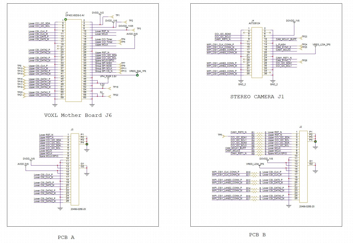
@Vinny Can you open the schematic of M0076 AXT Interposer schematic for easy debugging? Here is the schematic and made pcba but I can only one camera.
Hi @andrea_seock
OK, I think I understand what is happening. You made an adapter to convert M0076 to COAX, and it works, but then when you made one directly to VOXL 2 J6, it does not work.
Here are some things I note:- You need to use DOVDD_1V8 for DOVDD. The "VREG_S4A_1P8" notion although correct voltage is a different control. VREG_S4A_1P8 notation on our website is from VOXL 1 era, so apologies if that created confusion. It should still function, but it is not ideal and create backdrive
- I think the real issue is the reset for the second sensor. On M0076 we have what we call a "legacy" config, as I noted above, you need to use pin 32 from J6 here for "CAM_RST1_N"
- The schematic still does not appear to have all the valid connections needed. Many net names on J2 do not connect to J1 since they are different names. I took the liberty of trying to add annotations to show you the connections needed. The rest seems correct.
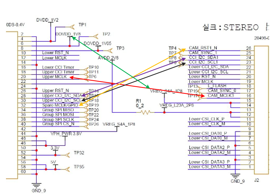
If you can adjust your SCH one more time to reflect the arrows I show, I can review one final time.
Thanks!
- You need to use DOVDD_1V8 for DOVDD. The "VREG_S4A_1P8" notion although correct voltage is a different control. VREG_S4A_1P8 notation on our website is from VOXL 1 era, so apologies if that created confusion. It should still function, but it is not ideal and create backdrive
-
Hi @andrea_seock
OK, I think I understand what is happening. You made an adapter to convert M0076 to COAX, and it works, but then when you made one directly to VOXL 2 J6, it does not work.
Here are some things I note:- You need to use DOVDD_1V8 for DOVDD. The "VREG_S4A_1P8" notion although correct voltage is a different control. VREG_S4A_1P8 notation on our website is from VOXL 1 era, so apologies if that created confusion. It should still function, but it is not ideal and create backdrive
- I think the real issue is the reset for the second sensor. On M0076 we have what we call a "legacy" config, as I noted above, you need to use pin 32 from J6 here for "CAM_RST1_N"
- The schematic still does not appear to have all the valid connections needed. Many net names on J2 do not connect to J1 since they are different names. I took the liberty of trying to add annotations to show you the connections needed. The rest seems correct.
If you can adjust your SCH one more time to reflect the arrows I show, I can review one final time.
Thanks!
- You need to use DOVDD_1V8 for DOVDD. The "VREG_S4A_1P8" notion although correct voltage is a different control. VREG_S4A_1P8 notation on our website is from VOXL 1 era, so apologies if that created confusion. It should still function, but it is not ideal and create backdrive
-
@Vinny Finally I got the goals. I really appreciate you. Check one more time please.
Hi @andrea_seock
That set of connections does appear to be correct now.
Keep us posted!
Hello! It looks like you're interested in this conversation, but you don't have an account yet.
Getting fed up of having to scroll through the same posts each visit? When you register for an account, you'll always come back to exactly where you were before, and choose to be notified of new replies (either via email, or push notification). You'll also be able to save bookmarks and upvote posts to show your appreciation to other community members.
With your input, this post could be even better 💗
Register Login