M0181 Pin Out and Electrical Diagram
-
@joseph-vale I think a lot of FLIR's docs are public domain, but we did not receive them that way, hence our reluctance. If you can be more specific as to what you need, I'll try my best.
Hi @Vinny
My apologies on the miscomms - I meant the connection the VOXL2 mating element. I've seen that pinout and thanks for resharing - but I wanted to also double check on the impedance matching and whatnot. Our IPEX cable has an impedance of 100ohms - is this consistent with your design? Do you do cross wiring / ESD protection? I'm not seeing these in the docs. Effectively are there any other design aspects we should be aware of making that board connection? We have all of the Hadron stuff we need for their pinouts and whatnot.
-
Hi @Vinny
My apologies on the miscomms - I meant the connection the VOXL2 mating element. I've seen that pinout and thanks for resharing - but I wanted to also double check on the impedance matching and whatnot. Our IPEX cable has an impedance of 100ohms - is this consistent with your design? Do you do cross wiring / ESD protection? I'm not seeing these in the docs. Effectively are there any other design aspects we should be aware of making that board connection? We have all of the Hadron stuff we need for their pinouts and whatnot.
Hi @joseph-vale
Great, thanks for clarifying.
Apologies our website is not always perfect. It is maintained by us Engineers, so we often take some info for granted. I am a few years delinquent in adding image sensor design guidance to our tech docs")
All our MIPI_CSI lines are indeed 100-Ohm Differential, so the IPEX mate will match.
We include ESD protection on all MIPI CSI and I2C and GPIO/MCLK signals at the VOXL 2 J6, J7, and J8 connectors, so no need to double protect (or you can impact the bus signal quality with the added capacitance).When you get to the point of generating a schematic, I will offer a courtesy review. Ping me on this thread again and then I can email you privately to share if you wish.
One thing we did on our Coax design was plan on always using the same 26-pin cable, so it is our adapters that vary in pinouts, but our cable is always the fully populate 26 conductor DF56 series.
For Boson/Hadron, we use multiple conductors of 5V. We set that based on the DCR spec of our coax cable, so with your IPIEX cables, you can do something similar to achieve success.
We were also advised by Hirose to NOT use the outer shield as current carrying, so for every +DC path, we have a return GND conductor.Keep us posted!
-
Hi @joseph-vale
Great, thanks for clarifying.
Apologies our website is not always perfect. It is maintained by us Engineers, so we often take some info for granted. I am a few years delinquent in adding image sensor design guidance to our tech docs
All our MIPI_CSI lines are indeed 100-Ohm Differential, so the IPEX mate will match.
We include ESD protection on all MIPI CSI and I2C and GPIO/MCLK signals at the VOXL 2 J6, J7, and J8 connectors, so no need to double protect (or you can impact the bus signal quality with the added capacitance).When you get to the point of generating a schematic, I will offer a courtesy review. Ping me on this thread again and then I can email you privately to share if you wish.
One thing we did on our Coax design was plan on always using the same 26-pin cable, so it is our adapters that vary in pinouts, but our cable is always the fully populate 26 conductor DF56 series.
For Boson/Hadron, we use multiple conductors of 5V. We set that based on the DCR spec of our coax cable, so with your IPIEX cables, you can do something similar to achieve success.
We were also advised by Hirose to NOT use the outer shield as current carrying, so for every +DC path, we have a return GND conductor.Keep us posted!
@Vinny hey man y'all have incredible support and responsiveness and honestly I'll take your docs over most anything I've dealt with on other projects. I'm an electrical / optical engineer myself so I feel that haha. I appreciate it and will follow up when ready!
-
@Vinny hey man y'all have incredible support and responsiveness and honestly I'll take your docs over most anything I've dealt with on other projects. I'm an electrical / optical engineer myself so I feel that haha. I appreciate it and will follow up when ready!
Thanks @joseph-vale for the kind words.
We will continue to try our best
Our success only comes with your success. -
Hi @joseph-vale
Great, thanks for clarifying.
Apologies our website is not always perfect. It is maintained by us Engineers, so we often take some info for granted. I am a few years delinquent in adding image sensor design guidance to our tech docs
All our MIPI_CSI lines are indeed 100-Ohm Differential, so the IPEX mate will match.
We include ESD protection on all MIPI CSI and I2C and GPIO/MCLK signals at the VOXL 2 J6, J7, and J8 connectors, so no need to double protect (or you can impact the bus signal quality with the added capacitance).When you get to the point of generating a schematic, I will offer a courtesy review. Ping me on this thread again and then I can email you privately to share if you wish.
One thing we did on our Coax design was plan on always using the same 26-pin cable, so it is our adapters that vary in pinouts, but our cable is always the fully populate 26 conductor DF56 series.
For Boson/Hadron, we use multiple conductors of 5V. We set that based on the DCR spec of our coax cable, so with your IPIEX cables, you can do something similar to achieve success.
We were also advised by Hirose to NOT use the outer shield as current carrying, so for every +DC path, we have a return GND conductor.Keep us posted!
Hello @Vinny , I am Fernando, and I am working on this project.
There was an error regarding the Impedance of the I-PEX cable. Each Micro-Coaxial has an impedance of 50 ohms, and for sure, the cable you are using is also 50 ohms.
My question is, how are you connecting each 100-ohm differential pair from the MIPI interface through each coaxial line?
Regards and thanks in advance
-
Hello @Vinny , I am Fernando, and I am working on this project.
There was an error regarding the Impedance of the I-PEX cable. Each Micro-Coaxial has an impedance of 50 ohms, and for sure, the cable you are using is also 50 ohms.
My question is, how are you connecting each 100-ohm differential pair from the MIPI interface through each coaxial line?
Regards and thanks in advance
Hi @Nando75
Yes, that is a fundamental limit of ALL uCoax that is not Twinax Impedance controlled conductors. Therefor all IPEX, Hirose, Molex, TE, etc (you name it) coax will fundamentally be limited in performance compared to true 100-ohm differential controlled impedance you can get from flex circuits or Samtec's Twinax. It is one of the many tradeoffs in our design space we need to make. As such, that is why we are firm on keeping the coax short and we do not sell any option longer than 180mm since at some point that small impedance offset and tolerances between two 50-ohm conductors compared to a true coupled 100-ohm may play a role.Hope this helps you.
Thanks! -
Hi @Nando75
Yes, that is a fundamental limit of ALL uCoax that is not Twinax Impedance controlled conductors. Therefor all IPEX, Hirose, Molex, TE, etc (you name it) coax will fundamentally be limited in performance compared to true 100-ohm differential controlled impedance you can get from flex circuits or Samtec's Twinax. It is one of the many tradeoffs in our design space we need to make. As such, that is why we are firm on keeping the coax short and we do not sell any option longer than 180mm since at some point that small impedance offset and tolerances between two 50-ohm conductors compared to a true coupled 100-ohm may play a role.Hope this helps you.
Thanks!Thanks, @Vinny, for your help.
Just to confirm, you're suggesting that an IPEX cable assembly like this one (https://www.digikey.com/en/products/detail/i-pex/81457-100B-02-D/22108838?gclsrc=aw.ds&gad_source=1&gad_campaignid=203759898&gbraid=0AAAAADrbLljG_0DgosYmSjn-L6wfiInDx&gclid=CjwKCAjwxrLHBhA2EiwAu9EdMyI0xVm4X54JIAOikP3zqiHT_KgnCN1m9s6Gd_ba0VRVhewe2lowKxoCYHAQAvD_BwE), with a length of 200mm (slightly longer than your suggested 180mm), could work if each line of the differential pair is carried over a separate coaxial cable.
Regards,
Fernando
-
Thanks, @Vinny, for your help.
Just to confirm, you're suggesting that an IPEX cable assembly like this one (https://www.digikey.com/en/products/detail/i-pex/81457-100B-02-D/22108838?gclsrc=aw.ds&gad_source=1&gad_campaignid=203759898&gbraid=0AAAAADrbLljG_0DgosYmSjn-L6wfiInDx&gclid=CjwKCAjwxrLHBhA2EiwAu9EdMyI0xVm4X54JIAOikP3zqiHT_KgnCN1m9s6Gd_ba0VRVhewe2lowKxoCYHAQAvD_BwE), with a length of 200mm (slightly longer than your suggested 180mm), could work if each line of the differential pair is carried over a separate coaxial cable.
Regards,
Fernando
Hi @Nando75
If it was less than 200mm, yes. 200mm is at your own risk, and make sure your SW team knows how to reach out and request slower MIPI CLK speeds in the event of signal integrity failures (camera failures).
Keep us posted.
Thanks! -
Hi @Nando75
If it was less than 200mm, yes. 200mm is at your own risk, and make sure your SW team knows how to reach out and request slower MIPI CLK speeds in the event of signal integrity failures (camera failures).
Keep us posted.
Thanks! -
@Vinny , and what about using this kind of flex cable https://www.digikey.com/en/products/detail/jae-electronics/JF08R0R051040UA/9477713 ?
It is supposed that it has an impedance of 100 ohms between pairsThanks in advance,
FernandoHi @Nando75
A shielded, impedance-controlled flex was our go-to solution in the early days, and we still offer a few legacy adapters that use it. These provide excellent signal integrity and EMI shielding. However, they’re limited in deployment flexibility; each flex must be meticulously designed for a specific routing path.Coax, on the other hand, greatly improves routing versatility and can be deployed across many platforms. The trade-off is reduced signal distance and slightly degraded signal integrity compared to a tuned flex.
Ultimately, it’s a system-level tradeoff. We’ve transitioned to coax as our mainstream solution in recent years, driven by customer demand for easier installation without the constraints of custom flex circuits.
Only your team can decide what's more important and hopefully we can enable you either way.
-
Hi @Nando75
A shielded, impedance-controlled flex was our go-to solution in the early days, and we still offer a few legacy adapters that use it. These provide excellent signal integrity and EMI shielding. However, they’re limited in deployment flexibility; each flex must be meticulously designed for a specific routing path.Coax, on the other hand, greatly improves routing versatility and can be deployed across many platforms. The trade-off is reduced signal distance and slightly degraded signal integrity compared to a tuned flex.
Ultimately, it’s a system-level tradeoff. We’ve transitioned to coax as our mainstream solution in recent years, driven by customer demand for easier installation without the constraints of custom flex circuits.
Only your team can decide what's more important and hopefully we can enable you either way.
We are moving forward with JAE Electronics flex cables.
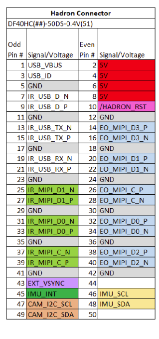
Regarding the pinout for the Camera Connectors, I have a question about the MIPI Lanes. We intend to connect the IR and Visible MIPI lanes from the HADRON 640 to the VOXL2. Additionally, we will connect the I2C lines to control the camera.
My primary question is: Can I utilize only one camera group, or will two camera groups be necessary? If a single camera group is feasible, I plan to use one 51-pin Flexible Cable (https://www.digikey.com/en/products/detail/jae-electronics/JF08R0R051040UA/9477713) to connect our breakout board to an adapter PCB for the Hirose connector.
This information is crucial for us to begin the schematic design.
Regards,
Fernando
-
We are moving forward with JAE Electronics flex cables.
Regarding the pinout for the Camera Connectors, I have a question about the MIPI Lanes. We intend to connect the IR and Visible MIPI lanes from the HADRON 640 to the VOXL2. Additionally, we will connect the I2C lines to control the camera.
My primary question is: Can I utilize only one camera group, or will two camera groups be necessary? If a single camera group is feasible, I plan to use one 51-pin Flexible Cable (https://www.digikey.com/en/products/detail/jae-electronics/JF08R0R051040UA/9477713) to connect our breakout board to an adapter PCB for the Hirose connector.
This information is crucial for us to begin the schematic design.
Regards,
Fernando
Hi @Nando75
For the Boson portion of the Hadron, you need a 2L MIPI CSI config and for the EO portion you need a full 4-L MIPI CSI port, so you will be consuming an entire "Camera Group" from VOXL 2 for this.
You will want to assign the "lower" group to the Boson Portion in 2L mode and the full 4L "upper" group to the EO portion such that our SW matches up easily. Here are some mapping tables we constructed early on for this you can use as a guide (color based mapping, so hopefully that comes through OK).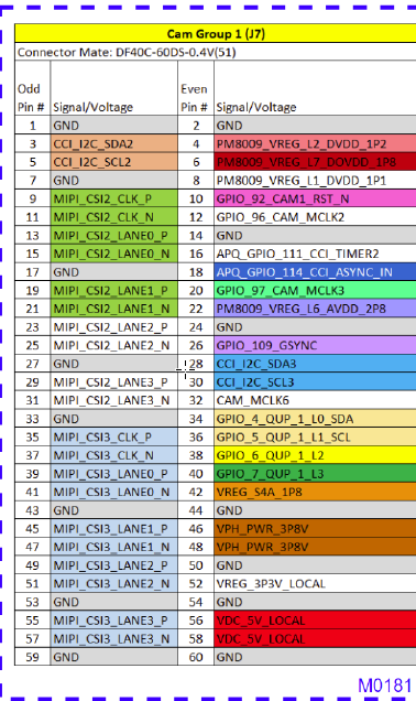
However, please double check this and also let us know when you are ready for a SCH review. Tag me again on the Forum when you are ready, then I can email you at the address used for your Forum registration so you can share your SCH with me for a review.
Hope this helped!
Thanks! -
Hi @Nando75
For the Boson portion of the Hadron, you need a 2L MIPI CSI config and for the EO portion you need a full 4-L MIPI CSI port, so you will be consuming an entire "Camera Group" from VOXL 2 for this.
You will want to assign the "lower" group to the Boson Portion in 2L mode and the full 4L "upper" group to the EO portion such that our SW matches up easily. Here are some mapping tables we constructed early on for this you can use as a guide (color based mapping, so hopefully that comes through OK).
However, please double check this and also let us know when you are ready for a SCH review. Tag me again on the Forum when you are ready, then I can email you at the address used for your Forum registration so you can share your SCH with me for a review.
Hope this helped!
Thanks!@Vinny I'm also creating my own adapter board to replaces M0181 adapter that connects the Hadron 640 to a 400mm 51-pin Flexible Cable and then connects to the VOXL2 J7 connector. Can I also send you my schematic for you to review? Thank you in advance.
-
@Vinny I'm also creating my own adapter board to replaces M0181 adapter that connects the Hadron 640 to a 400mm 51-pin Flexible Cable and then connects to the VOXL2 J7 connector. Can I also send you my schematic for you to review? Thank you in advance.
Hi @SDSU_Drones
You bet.... emailing you now!
Thanks!
Vinny -
Hi @SDSU_Drones
You bet.... emailing you now!
Thanks!
Vinny@SDSU_Drones
Just to close this out, I emailed you a review report. Hope that helps you along your way.Thanks!
Vinny -
@SDSU_Drones
Just to close this out, I emailed you a review report. Hope that helps you along your way.Thanks!
Vinny@Vinny Is J8 still not supported? I'm looking at using a hadron and two M0166 sensors, which may not be possible without J8.
-
@Vinny Is J8 still not supported? I'm looking at using a hadron and two M0166 sensors, which may not be possible without J8.
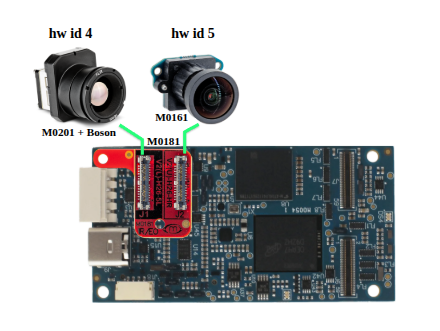
@Dan-Jennings , M0181 can be used to enable a Boson and another hires or tracking camera (or Hadron combo), see diagram below. You would need to use the kernal variant 1.0.1 (same one used for M0173, which I am assuming you are already using).
So basically, you can use any standard config C26-C29 + two more cameras connected to VOXL2 J8. Please note that VOXL2 J8 shares CCI (i2c) buses with J6 and J7, so you have to be a little careful about what cameras you connect to J8 to avoid i2c address conflicts. I am going to put together some more information on that soon. But if you are adding a Hadron or Boson + IMX412 to J8, there will be no conflict.
Please let us know if you have any other questions.
Alex
Hello! It looks like you're interested in this conversation, but you don't have an account yet.
Getting fed up of having to scroll through the same posts each visit? When you register for an account, you'll always come back to exactly where you were before, and choose to be notified of new replies (either via email, or push notification). You'll also be able to save bookmarks and upvote posts to show your appreciation to other community members.
With your input, this post could be even better 💗
Register Login