Continuous bench supply with VOXL FPV Racing 4-in-1 ESC (M0138) — braking disable + TVS protection guidance
-
We’re bringing up a system using a bench power supply at ~25 VDC with the VOXL FPV Racing 4-in-1 ESC (M0138) and want to avoid any risk from regenerative braking / bus overvoltage.
Braking disable / configuration
- Can you confirm whether brake_to_stop exists and is supported on M0138, and whether setting brake_to_stop = 0 will ensure the ESC does not brake on stop/timeout (coast instead)?
- Is there any supported method on M0138 to disable regenerative braking during commanded deceleration (not just stop/timeout), or is that currently not supported in firmware?
TVS diode protection at 25 VDC bench supply
Given your regenerative braking note about power supplies not sinking current and the TVS dissipating energy during clamp, what is your recommended protection approach for M0138 when using a bench supply near 25V? Specifically:- What are the TVS clamp voltage and power/energy limits (part number or equivalent rating)?
* Recommended external mitigation: would you prefer
* a 4-quadrant / sink-capable supply,
* adding an external battery/supercap “sink” in parallel,
* an external brake/shunt (dump resistor/regulator),
* additional bulk capacitance (and any sizing guidance),
* or other best practices? - Any operational limits you recommend for bench testing (e.g., avoid step-down commands, limit max PWM / rpm, etc.)?
If you have a recommended parameter set or test procedure specifically for M0138 + bench supply bring-up, we’d appreciate it.
Hi @austin-c ,
Please see answers below:
brake_to_stopparameter does exit and it works. setting it to 0 will result in the motor coasting to a stop when it is commanded to stop or there is a command timeout. it is used here : link- the hardware supports disabling regenerative braking (we have tested this before), but the software does not support disabling regenerative braking during motor control
- the TVS breakdown voltage is around 29-30V. You can actually test this by slowly increasing voltage on the power supply (in 0.1V increments) and observe the current draw increase from nominally low value (be careful)
If you would like to test with a power supply, that's fine, but you have to be careful about the types of tests you are doing. Please understand the following:
- regenerative braking will happen any time there is a transition from higher rpm to a lower rpm
- this will happen regardless whether the ESC is rpm control mode or power control because that is a principle of "synchronous rectification" which is a technique for controlling mosfets (widely used on most ESCs). Any time the back-emf of the motor is higher than the average applied voltage, the regenerative current will flow back into the battery or power supply (roughly speaking).
In general, here are our guidelines for testing with a power supply
- keep in mind that the dynamic response (even with rpm increase) will be different from a battery, as the battery typically has lower output impedance from a power supply
- testing steady state response or continuous spinning with slow transitions is a perfect applications
- aggressive transitions from low to high rpm (or from low to high power) are ok
- avoid aggressive transitions from high to low rpm, since that's when the back-emf will be generated
- we actually have a test script voxl-esc-spin-step.py which shows you how to you can use the control software to slew rate limit the commands to avoid fast up or down transitions. you can use a similar approach for your bench testing.
- exploring the TVS diode specs (clamping voltage) can be done using an unloaded motor, where the energy stored in the motor is small, so the TVS diode can absorb the regen energy. You can do a small step test with unloaded motor and see what what voltage the voltage spike gets clipped. There is a risk of burning out the TVS diode if the test is done with a loaded motor with a large high->low transition
- avoid loaded motor step-down tests while using a power supply
- set the
brake_to_stopesc parameter to 0 and stop the script or send zero rpm/ power in order to stop the motor (or just stop sending commands) instead of sending low rpm before 0 rpm. - adding external capacitance and an additional array of similar TVS diodes (placed as close as possible to the ESC) will help reduce (using capacitors) and absorb (additional tvs diodes to distribute the heat) the regen spikes .
- sink-capable power supplies are usually expensive, may not be worth it, depending on what you are trying to do. If you are trying to test performance of the motor using a power supply that models the battery (a battery simulator), that would work, but would be even more expensive
")
What kind of tests are you planning to run? I can provide more guidance.
Alex
-
Hi @austin-c ,
Please see answers below:
brake_to_stopparameter does exit and it works. setting it to 0 will result in the motor coasting to a stop when it is commanded to stop or there is a command timeout. it is used here : link- the hardware supports disabling regenerative braking (we have tested this before), but the software does not support disabling regenerative braking during motor control
- the TVS breakdown voltage is around 29-30V. You can actually test this by slowly increasing voltage on the power supply (in 0.1V increments) and observe the current draw increase from nominally low value (be careful)
If you would like to test with a power supply, that's fine, but you have to be careful about the types of tests you are doing. Please understand the following:
- regenerative braking will happen any time there is a transition from higher rpm to a lower rpm
- this will happen regardless whether the ESC is rpm control mode or power control because that is a principle of "synchronous rectification" which is a technique for controlling mosfets (widely used on most ESCs). Any time the back-emf of the motor is higher than the average applied voltage, the regenerative current will flow back into the battery or power supply (roughly speaking).
In general, here are our guidelines for testing with a power supply
- keep in mind that the dynamic response (even with rpm increase) will be different from a battery, as the battery typically has lower output impedance from a power supply
- testing steady state response or continuous spinning with slow transitions is a perfect applications
- aggressive transitions from low to high rpm (or from low to high power) are ok
- avoid aggressive transitions from high to low rpm, since that's when the back-emf will be generated
- we actually have a test script voxl-esc-spin-step.py which shows you how to you can use the control software to slew rate limit the commands to avoid fast up or down transitions. you can use a similar approach for your bench testing.
- exploring the TVS diode specs (clamping voltage) can be done using an unloaded motor, where the energy stored in the motor is small, so the TVS diode can absorb the regen energy. You can do a small step test with unloaded motor and see what what voltage the voltage spike gets clipped. There is a risk of burning out the TVS diode if the test is done with a loaded motor with a large high->low transition
- avoid loaded motor step-down tests while using a power supply
- set the
brake_to_stopesc parameter to 0 and stop the script or send zero rpm/ power in order to stop the motor (or just stop sending commands) instead of sending low rpm before 0 rpm. - adding external capacitance and an additional array of similar TVS diodes (placed as close as possible to the ESC) will help reduce (using capacitors) and absorb (additional tvs diodes to distribute the heat) the regen spikes .
- sink-capable power supplies are usually expensive, may not be worth it, depending on what you are trying to do. If you are trying to test performance of the motor using a power supply that models the battery (a battery simulator), that would work, but would be even more expensive
What kind of tests are you planning to run? I can provide more guidance.
Alex
I went ahead and ran a few tests with a 11A power supply set to 25V.
Using M0138 ESC, Xing2 2207 1855kV motor and 5x4x3 propeller
Both tests using the same
voxl-esccommand, executed on a linux pc that is connected to the ESC directly via usb to serial adapter.Test command:
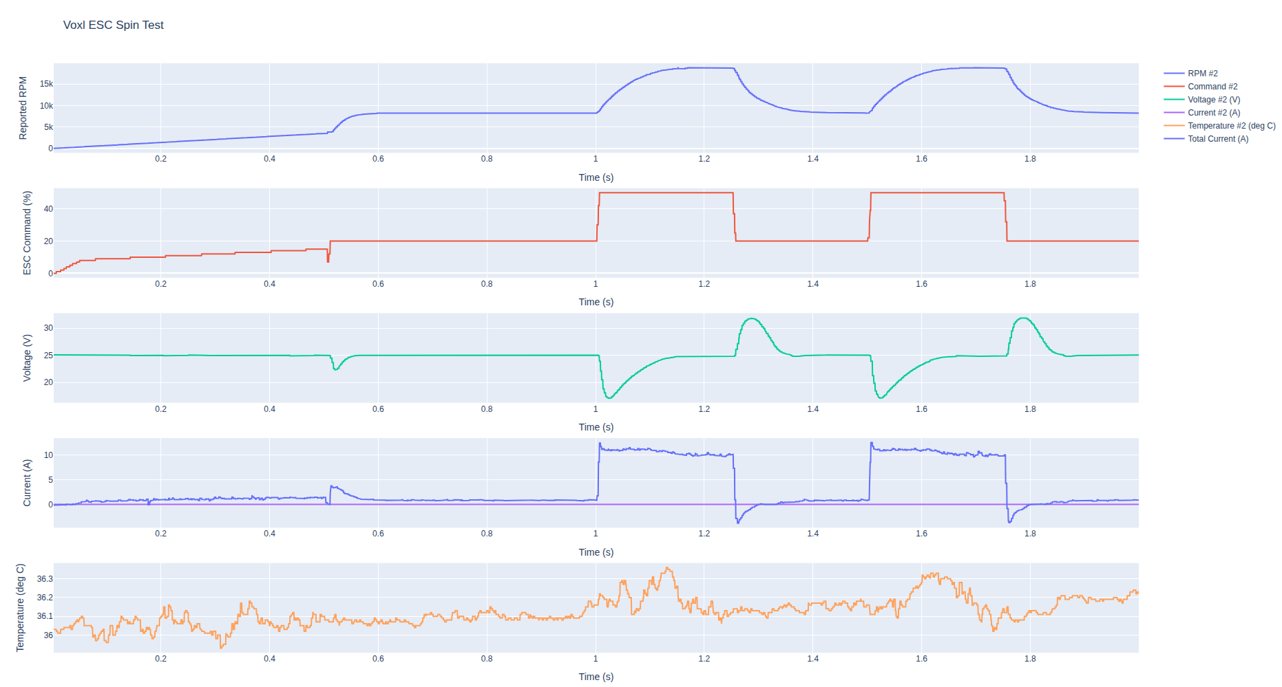
./voxl-esc-spin-step.py --id 2 --power 20 --step-amplitude 30 --step-frequency 2.0 --timeout 2.0 --cmd-rate 2000 --enable-plot 1Results / notes:
- no load test showed a higher peak of 33.8V vs about 31.8V loaded with prop, which actually makes sense because the no load motor RPM is higher (larger back-emf).
- only testing one channel at a time to reduce voltage spike
- start with small step to get a sense of regenerative voltage rize
- short test to avoid any damage
- ran the test on ESC id 2, so that total current is measured and displayed
- this motor has pretty high kV and small size propeller, so it decelerates quickly. However, other motor and larger propeller combinations (and larger rpm changes) may generate a lot larger spike (if the motor spends more time at higher rpms).
- also did a test to see at which point the ESC starts drawing more current - TVS diode starts conducting (short voltage increase on the power supply, i.e. for 1 second). As the TVS diode warms up, the current drops a bit because of the diode characteristics (breakdown voltage increases with temperature). However, the performance of TVS diode varies significantly across the voltage range, so it cannot be used for any exact measurements.
- 25-27.5V : 0.02A
- 28V: 0.035A
- 29V: 0.09A
- 30V: 0.15A
- 31V: 0.20A
..
Test 1: no propeller
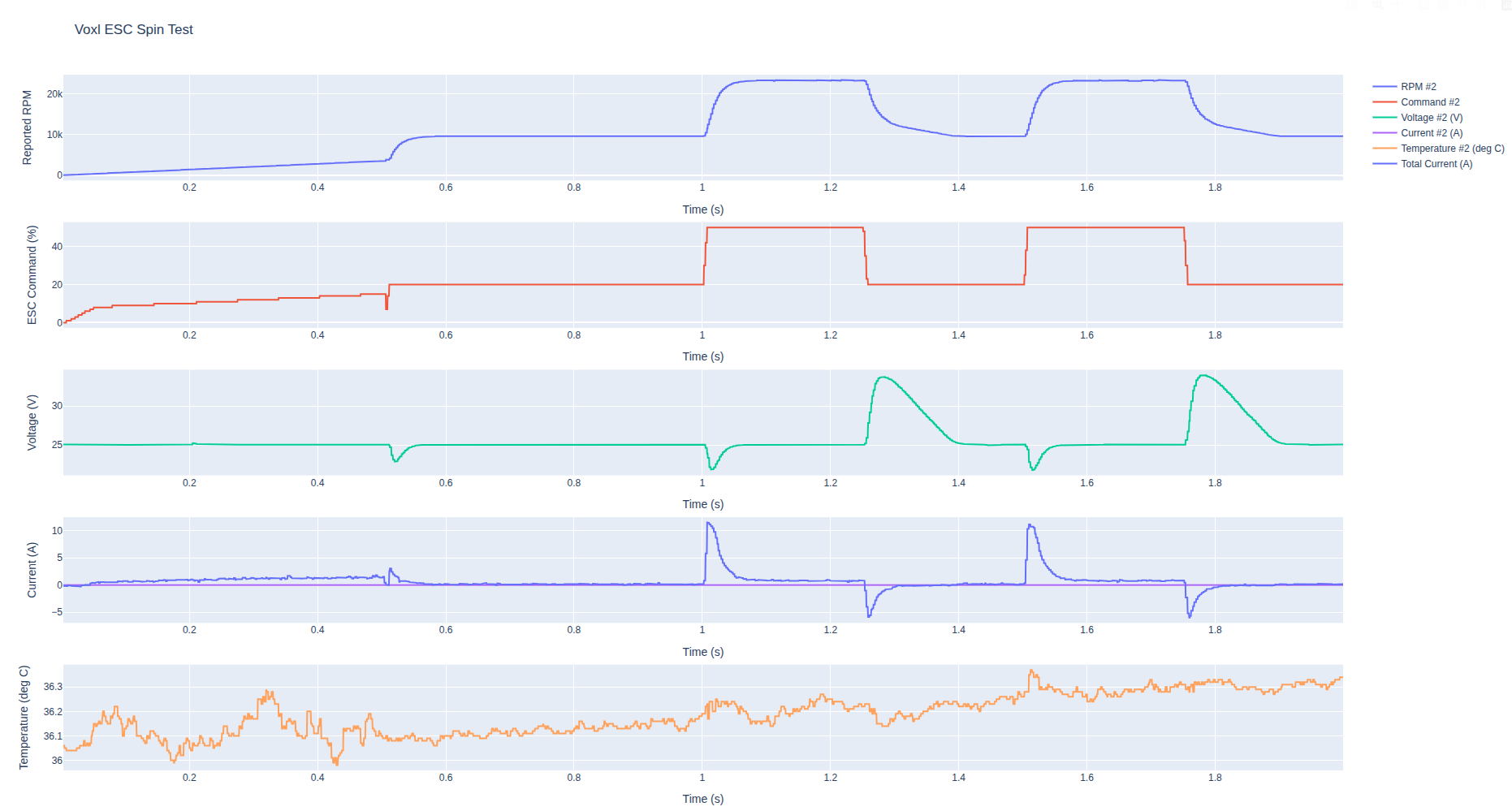
Test 2: with propeller
-
I went ahead and ran a few tests with a 11A power supply set to 25V.
Using M0138 ESC, Xing2 2207 1855kV motor and 5x4x3 propeller
Both tests using the same
voxl-esccommand, executed on a linux pc that is connected to the ESC directly via usb to serial adapter.Test command:
./voxl-esc-spin-step.py --id 2 --power 20 --step-amplitude 30 --step-frequency 2.0 --timeout 2.0 --cmd-rate 2000 --enable-plot 1Results / notes:
- no load test showed a higher peak of 33.8V vs about 31.8V loaded with prop, which actually makes sense because the no load motor RPM is higher (larger back-emf).
- only testing one channel at a time to reduce voltage spike
- start with small step to get a sense of regenerative voltage rize
- short test to avoid any damage
- ran the test on ESC id 2, so that total current is measured and displayed
- this motor has pretty high kV and small size propeller, so it decelerates quickly. However, other motor and larger propeller combinations (and larger rpm changes) may generate a lot larger spike (if the motor spends more time at higher rpms).
- also did a test to see at which point the ESC starts drawing more current - TVS diode starts conducting (short voltage increase on the power supply, i.e. for 1 second). As the TVS diode warms up, the current drops a bit because of the diode characteristics (breakdown voltage increases with temperature). However, the performance of TVS diode varies significantly across the voltage range, so it cannot be used for any exact measurements.
- 25-27.5V : 0.02A
- 28V: 0.035A
- 29V: 0.09A
- 30V: 0.15A
- 31V: 0.20A
..
Test 1: no propeller
Test 2: with propeller
For context on our side: we’re looking at an MN4006 380KV motor with a 13” prop, and our system will be powered from an external DC source via a DC-DC power module (not a conventional LiPo-style source), so we’re trying to be very deliberate about regen / bus overvoltage from decel events.
We’re still in feasibility / design phase and don’t have physical hardware spun yet, so we’re leaning heavily on your recommendations to make sure we bake in the right mitigations from the start.
Based on what you shared, our intended approach is:
- Configure for no braking: brake_to_stop=0 (coast on stop/timeout).
- Treat decel as the main risk: implement slew-rate limiting / avoid hard high low RPM steps (similar to the voxl-esc-spin-step.py approach you referenced).
- Design the input protection around an external DC bus:
- Bulk capacitance at the ESC input, physically close to the ESC, and
- Additional parallel TVS near the ESC input to share transient energy/thermal load.
Since we don’t have hardware assembled, could you sanity-check a couple design-direction items?
- For a larger inertia setup (13” prop), do you have a starting point / rule-of-thumb for how much bulk capacitance you’d place at the ESC input (order of magnitude is fine)?
- When you say “parallel TVS,” is your intent more like multiple identical parts in parallel close to the ESC, or targeting a total TVS power/energy capability? Any rough guidance there would help.
- Is there anything else you’d recommend we do upstream (e.g., supply-side clamp strategy, or constraints on allowable decel) given the source may not be able to sink current?
- Really appreciate your help we’ll incorporate your guidance into the design and share what we decide / what we observe once we get to bench testing.
-
For context on our side: we’re looking at an MN4006 380KV motor with a 13” prop, and our system will be powered from an external DC source via a DC-DC power module (not a conventional LiPo-style source), so we’re trying to be very deliberate about regen / bus overvoltage from decel events.
We’re still in feasibility / design phase and don’t have physical hardware spun yet, so we’re leaning heavily on your recommendations to make sure we bake in the right mitigations from the start.
Based on what you shared, our intended approach is:
- Configure for no braking: brake_to_stop=0 (coast on stop/timeout).
- Treat decel as the main risk: implement slew-rate limiting / avoid hard high low RPM steps (similar to the voxl-esc-spin-step.py approach you referenced).
- Design the input protection around an external DC bus:
- Bulk capacitance at the ESC input, physically close to the ESC, and
- Additional parallel TVS near the ESC input to share transient energy/thermal load.
Since we don’t have hardware assembled, could you sanity-check a couple design-direction items?
- For a larger inertia setup (13” prop), do you have a starting point / rule-of-thumb for how much bulk capacitance you’d place at the ESC input (order of magnitude is fine)?
- When you say “parallel TVS,” is your intent more like multiple identical parts in parallel close to the ESC, or targeting a total TVS power/energy capability? Any rough guidance there would help.
- Is there anything else you’d recommend we do upstream (e.g., supply-side clamp strategy, or constraints on allowable decel) given the source may not be able to sink current?
- Really appreciate your help we’ll incorporate your guidance into the design and share what we decide / what we observe once we get to bench testing.
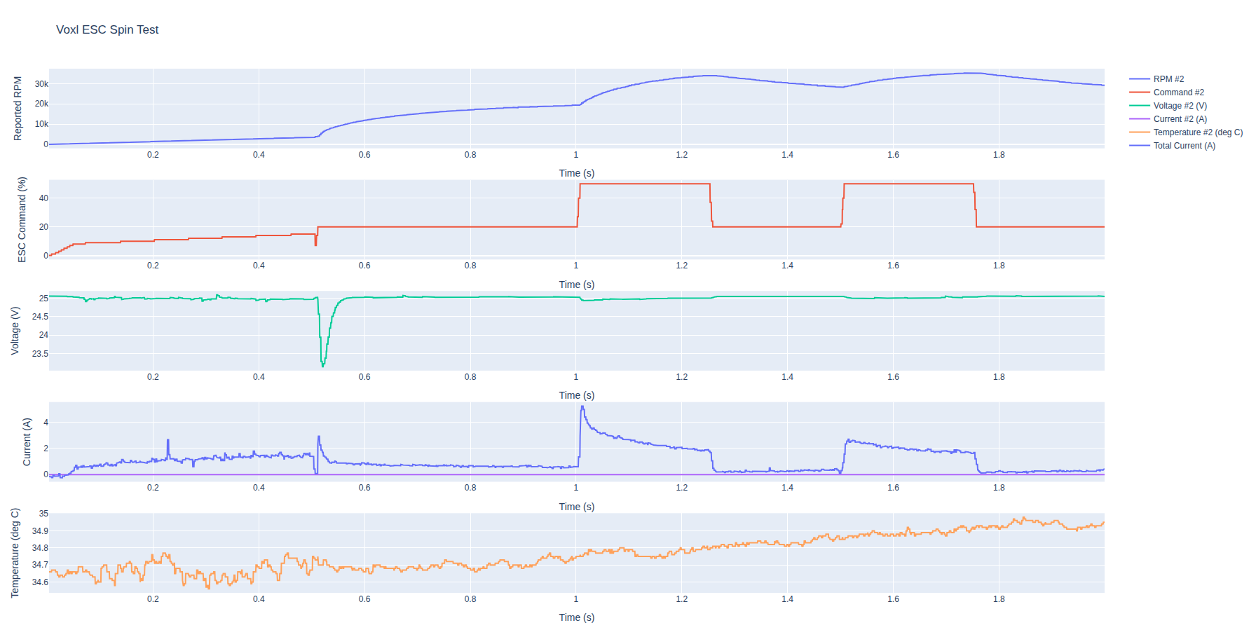
@austin-c , i just checked and actually we have an option to disable regen braking, it is just not available yet via a param. Here is the test result with same setup (no prop) with regen braking disabled. You can see that the motor takes a long time to coast down, but there is no regen voltage spike or regen current at all. If you application does not require rapid rpm change (high to low), then it will work fine.
We have not tested this in a while, but at some point we did testing for an application with a smart battery which did not like being re-charged with the regen current.
I will see if we can enable this via param or worst case scenario I can share the latest firmware with regen off.
Regarding your other questions:
- i don't think you can put enough capacitance to really absorb all the charge that needs to be stored.. You could do some basic calculations using the current spikes to see how much capacitance you would need, but it think it would be a LOT.
- regarding multiple TVS diodes, yes just connect an array of them in parallel, simply to distribute the energy (heat) across multiple diodes to prevent them from overheating (also can choose larger package, but they all would have to have same specs).
Also, since your motor is low kv, i just want to make sure you saw this document (you probably did, just double checking) : https://gitlab.com/voxl-public/voxl-sdk/utilities/voxl-esc/-/blob/master/voxl-esc-tools/doc/low_kv_motor_tuning.md
Actually the app note for low kv tuning was using the Tmotor MN4006 motor with even larger 15 inch propeller (see Tuning Example section). It should work fine with appropriate parameters, we can help tuning if you tell me the exact propeller.
motor MN4006-23 380kV, 18N24P winding configuration
12 pole pairs (24/2)
15-inch propeller MS1503
6S battery voltage
Alex
-
@austin-c , i just checked and actually we have an option to disable regen braking, it is just not available yet via a param. Here is the test result with same setup (no prop) with regen braking disabled. You can see that the motor takes a long time to coast down, but there is no regen voltage spike or regen current at all. If you application does not require rapid rpm change (high to low), then it will work fine.
We have not tested this in a while, but at some point we did testing for an application with a smart battery which did not like being re-charged with the regen current.
I will see if we can enable this via param or worst case scenario I can share the latest firmware with regen off.
Regarding your other questions:
- i don't think you can put enough capacitance to really absorb all the charge that needs to be stored.. You could do some basic calculations using the current spikes to see how much capacitance you would need, but it think it would be a LOT.
- regarding multiple TVS diodes, yes just connect an array of them in parallel, simply to distribute the energy (heat) across multiple diodes to prevent them from overheating (also can choose larger package, but they all would have to have same specs).
Also, since your motor is low kv, i just want to make sure you saw this document (you probably did, just double checking) : https://gitlab.com/voxl-public/voxl-sdk/utilities/voxl-esc/-/blob/master/voxl-esc-tools/doc/low_kv_motor_tuning.md
Actually the app note for low kv tuning was using the Tmotor MN4006 motor with even larger 15 inch propeller (see Tuning Example section). It should work fine with appropriate parameters, we can help tuning if you tell me the exact propeller.
motor MN4006-23 380kV, 18N24P winding configuration
12 pole pairs (24/2)
15-inch propeller MS1503
6S battery voltage
Alex
Also, you should note - the motor's open loop RPM speed increases at the same power setting -- this is a consequence of not having active freewheeling. This does not mean, though, that if active freewheeling (regen braking) is disabled, that you would get higher max rpm or more efficiency. It just changes the motor pwm % to rpm mapping.
Alex
-
Also, you should note - the motor's open loop RPM speed increases at the same power setting -- this is a consequence of not having active freewheeling. This does not mean, though, that if active freewheeling (regen braking) is disabled, that you would get higher max rpm or more efficiency. It just changes the motor pwm % to rpm mapping.
Alex
@Alex-Kushleyev thank you, this is exactly what we were hoping to hear.
Given our power architecture, we’d strongly prefer to disable regenerative braking entirely to avoid any back-feed / bus overvoltage corner cases. We’re effectively hovering with “infinite” available source power, so we’re not trying to harvest regen energy coasting down is totally acceptable for our use case.
For the exact prop: we’re currently baselining an APC 13x5.5MRF-R(B) (13” diameter, 5.5” pitch, folding multi-rotor blades). https://www.apcprop.com/product/13x5-5mrf-rb/?v=7516fd43adaa
We can definitely focus on tuning once we’re on the bench. We did see the low-kV tuning note you linked (and it’s reassuring you’ve already used MN4006 with an even larger prop in the example).
If you’re able to expose the “regen off” option via a param or share a firmware build with regen disabled, we’d love to start with that as our default configuration. Are there any specific caveats you want us to be aware of when regen is disabled beyond the slower coast-down / mapping differences you mentioned?
Thanks again your tests and guidance are helping us de-risk the design decisions before we commit to hardware.
-
@Alex-Kushleyev thank you, this is exactly what we were hoping to hear.
Given our power architecture, we’d strongly prefer to disable regenerative braking entirely to avoid any back-feed / bus overvoltage corner cases. We’re effectively hovering with “infinite” available source power, so we’re not trying to harvest regen energy coasting down is totally acceptable for our use case.
For the exact prop: we’re currently baselining an APC 13x5.5MRF-R(B) (13” diameter, 5.5” pitch, folding multi-rotor blades). https://www.apcprop.com/product/13x5-5mrf-rb/?v=7516fd43adaa
We can definitely focus on tuning once we’re on the bench. We did see the low-kV tuning note you linked (and it’s reassuring you’ve already used MN4006 with an even larger prop in the example).
If you’re able to expose the “regen off” option via a param or share a firmware build with regen disabled, we’d love to start with that as our default configuration. Are there any specific caveats you want us to be aware of when regen is disabled beyond the slower coast-down / mapping differences you mentioned?
Thanks again your tests and guidance are helping us de-risk the design decisions before we commit to hardware.
@austin-c , i don't have any concerns for disabling active freewheeling other than the fact that the responsiveness of the ESC will be reduced, as the RPM reduction will be purely due to air drag acting on the propeller (and small friction in the motor).
I can set up the MN4006 motor with a 13 or 15 inch propeller, do a RPM control tune and compare the RPM response results with regen on and off. This is actually pretty quick to do, i will try to do it in the next few days.
Please ping me if you don't hear back by early next week
Alex
-
@Alex-Kushleyev appreciate the assist here. I'll follow up next week!
Hi @austin-c ,
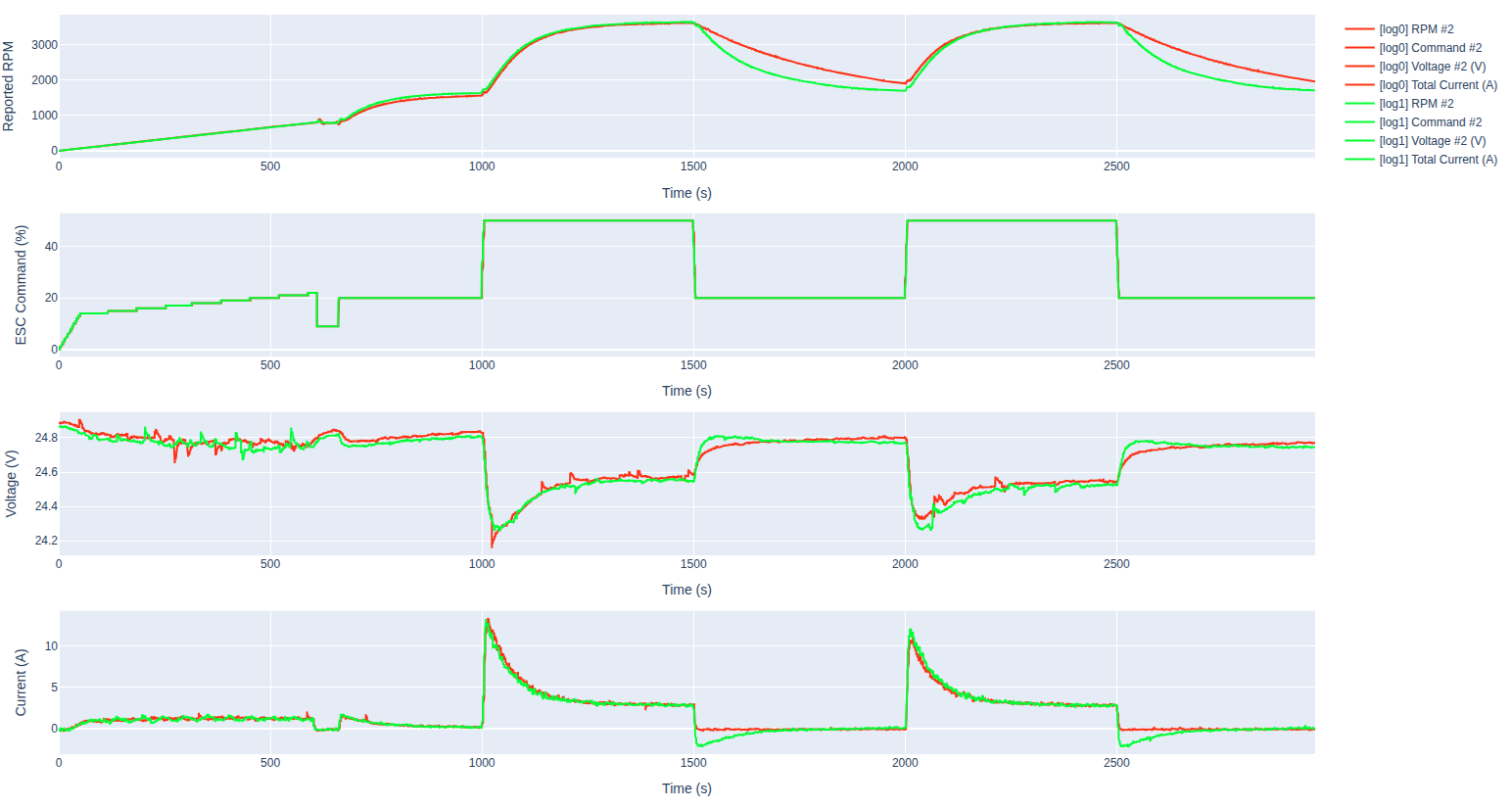
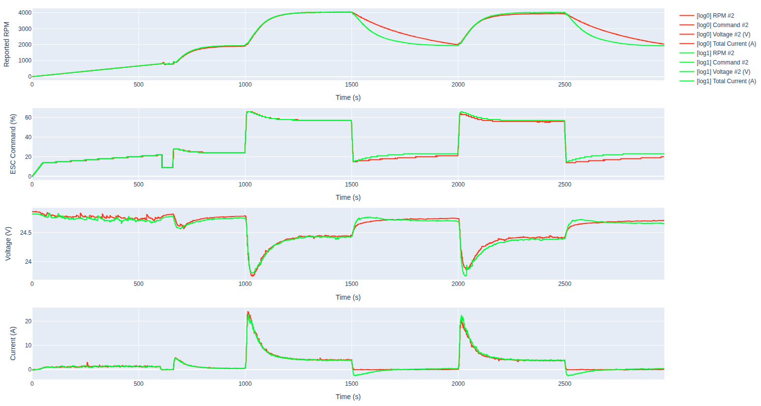
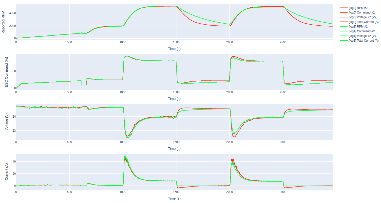
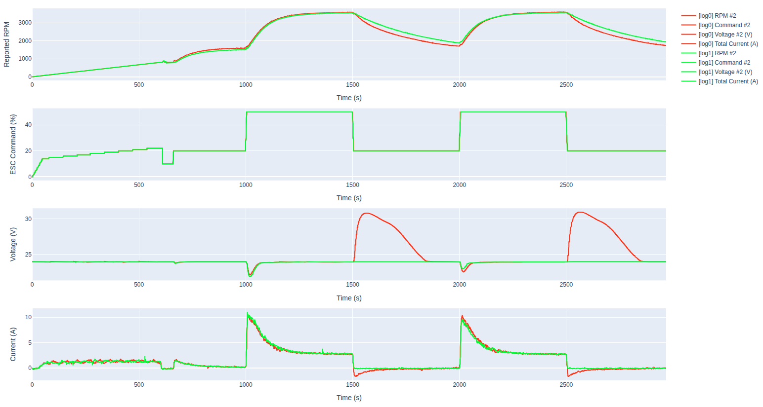
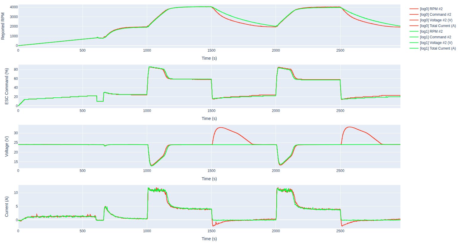
I ran some tests with Tmotor MN4006-23 380kV and 15-inch MS1503 propeller, using M0138 ESC. Tests were done with a battery and a power supply. Please see results below.
- the colors may vary from plot to plot, but the one with slower deceleration is "regen off"
- did not run large rpm steps on power supply because the power supply was already current limited
- regen peaks were 31V (pwm step) and 33V (rpm step) for the power supply test
- motor acceleration is almost identical for regen on/off tests
- very large difference in motor deceleration, especially for the large high-to-low rpm transitions
- also note that the power supply tests result in slower deceleration even with regen on (because the power supply cannot sink the current)
- TVS diode did not blow out in this test, because the spikes were short and only a few at a time
Please note that, in theory, it is possible to decelerate the motor faster without regenerative braking (by applying more power, but out of phase), however we do not have this implemented.
If the motor deceleration is slowed down due to lack of regenerative braking, the attitude control will be affected because the motor response is highly asymmetric for acceleration vs deceleration. Overall, this will result in effectively reducing the average responsiveness of the motor, so you would need to decrease control gains and probably will not be able to handle large disturbances very well and cause oscillations if not tuned properly.
Please review the plots (which are not surprising), and we can discuss further..
Alex
6S battery, Power step test:
6S battery, RPM small step test
6S battery, RPM large step test
11A Power Supply, Power step test:
11A Power Supply, RPM small step test
- the colors may vary from plot to plot, but the one with slower deceleration is "regen off"
-
Hi @austin-c ,
I ran some tests with Tmotor MN4006-23 380kV and 15-inch MS1503 propeller, using M0138 ESC. Tests were done with a battery and a power supply. Please see results below.
- the colors may vary from plot to plot, but the one with slower deceleration is "regen off"
- did not run large rpm steps on power supply because the power supply was already current limited
- regen peaks were 31V (pwm step) and 33V (rpm step) for the power supply test
- motor acceleration is almost identical for regen on/off tests
- very large difference in motor deceleration, especially for the large high-to-low rpm transitions
- also note that the power supply tests result in slower deceleration even with regen on (because the power supply cannot sink the current)
- TVS diode did not blow out in this test, because the spikes were short and only a few at a time
Please note that, in theory, it is possible to decelerate the motor faster without regenerative braking (by applying more power, but out of phase), however we do not have this implemented.
If the motor deceleration is slowed down due to lack of regenerative braking, the attitude control will be affected because the motor response is highly asymmetric for acceleration vs deceleration. Overall, this will result in effectively reducing the average responsiveness of the motor, so you would need to decrease control gains and probably will not be able to handle large disturbances very well and cause oscillations if not tuned properly.
Please review the plots (which are not surprising), and we can discuss further..
Alex
6S battery, Power step test:
6S battery, RPM small step test
6S battery, RPM large step test
11A Power Supply, Power step test:
11A Power Supply, RPM small step test
@Alex-Kushleyev That’s very helpful if disabling regenerative braking is working as intended, then it sounds like that addresses the primary concern on our bench-supply side.
From the flight-controller dynamics side, we’d still generally prefer to keep braking enabled in the long run, but handling the FC tuning impact is something we’re comfortable with. The main blocker for us has been finding a clean way to absorb regenerative energy on the bench supply during decel events.
Given that regen disable appears to solve that issue, we’ll plan to proceed with controlled validation on our motor/prop combination while monitoring bus voltage during transients.
A couple follow-up questions:
- list item Would you recommend exposing regenerative braking disable as a user parameter, or is this better handled as a custom firmware build for this application?
- list item Did you end up making any ESC tuning parameter changes when testing in this mode, especially for a lower-kV / larger-prop setup? If so, would you be willing to share those changes?
- the colors may vary from plot to plot, but the one with slower deceleration is "regen off"
-
@Alex-Kushleyev That’s very helpful if disabling regenerative braking is working as intended, then it sounds like that addresses the primary concern on our bench-supply side.
From the flight-controller dynamics side, we’d still generally prefer to keep braking enabled in the long run, but handling the FC tuning impact is something we’re comfortable with. The main blocker for us has been finding a clean way to absorb regenerative energy on the bench supply during decel events.
Given that regen disable appears to solve that issue, we’ll plan to proceed with controlled validation on our motor/prop combination while monitoring bus voltage during transients.
A couple follow-up questions:
- list item Would you recommend exposing regenerative braking disable as a user parameter, or is this better handled as a custom firmware build for this application?
- list item Did you end up making any ESC tuning parameter changes when testing in this mode, especially for a lower-kV / larger-prop setup? If so, would you be willing to share those changes?
Hi @austin-c ,
You can find the latest M0138 firmware with regen completely disabled here
Also, I added the esc config that i've been using for testing here
For step tests, i have been using pretty aggressive step command:
./voxl-esc-spin-step.py --id 2 --rpm 2000 --step-amplitude 4000 --step-frequency 2.0 --timeout 2.0 --cmd-rate 2000 --enable-plot 1In order to make the ESC not de-sync (due to long demag time of the motor), the following params were adjusted:
max_rpm_deltaset to 4000 (you can go lower), to cap the maximum rpm transitions. Although in my test, the step is 4000, so this had no effecttiming_advance: 45 -- this is pretty high commutation advance to trigger commutation earlier so that there is more time for back-emf sensing -- high advance wiil reduce motor efficiency and will cause the motor to heat up a bit moresense_advance: 30 -- delay back-emf sensing so that we don't sample back-emf during the motor coil demagnetization- more details : https://gitlab.com/voxl-public/voxl-sdk/utilities/voxl-esc/-/blob/dev/voxl-esc-tools/doc/low_kv_motor_tuning.md
I had another thought.. What if you use a small battery to absorb the voltage spikes? Basically hook up a 6-7S battery with a beefy Schottyky diode (10A) set up with Cathode (negative) pointing to the battery.
- you will have to make sure the power supply voltage never exceeds battery voltage + diode drop.
- you will also need to make sure that you don't over-charge the battery with repeated spike absorption.. It is possible to have some sort of self-discharge circuit to slowly discharge the battery to a certain voltage (using a Zener diode + resistor or something similar).
Anyway, just an idea..
Try out the no-regen firmware..
Alex
Hello! It looks like you're interested in this conversation, but you don't have an account yet.
Getting fed up of having to scroll through the same posts each visit? When you register for an account, you'll always come back to exactly where you were before, and choose to be notified of new replies (either via email, or push notification). You'll also be able to save bookmarks and upvote posts to show your appreciation to other community members.
With your input, this post could be even better 💗
Register Login