PWM
-
I am able to use the PWM command line tool to change the parameters and enable the PWM on the board. I'm using the PWM example to try and do it programmatically.
-
The PWM outputs at the lower level are configured here via the timers, as far as pinmappings:
https://github.com/PX4/PX4-Autopilot/blob/master/boards/modalai/fc-v1/src/timer_config.cppThe actual outputs get heavily controlled via mixers, like this;
https://github.com/PX4/PX4-Autopilot/blob/master/src/drivers/pwm_out/PWMOut.cpp#L552Does you application get anything from PX4 (e.g. maybe you implement with the 'OutputModuleInterface' ) or is it totally a roll you own?
-
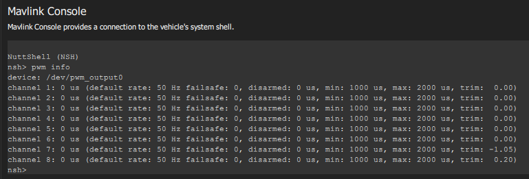
My plan was to use the pwm.cpp file as a reference, since I was previously able to use it to adjust the PWM output on a channel. See image.

However, now that I'm ready for the PWM development I can't seem to access the PWM channels as no PWM device shows up. I have tried this on two Flight Cores, both recently purchased. The Flight Core I used for the initial test shown in the image was put in the field but is being shipped back to me.
I ran my own firmware, I pulled fresh code from github, and for the second board I ran it without making any changes. None of these show a PWM device.
Is there some other configuration that is required to enable the PWM driver that I may be missing?
-
Hi @Andrew-Keefe ,
On the setup that doesn't have a PWM device, have you selected any airframe? I've seen this is the mixer isn't loaded, and the mixer not loading is normally from no airframe (although you are doing some custom stuff, so not positive).
This is where the output device gets selected:
https://github.com/PX4/PX4-Autopilot/blob/master/ROMFS/px4fmu_common/init.d/rc.interface#L157
-
I'm sure that's it. I remember now that I had selected a different airframe last time, though I'm not really using the airframe for my code.
-
@modaltb I have my PWM code working when I run it manually, but it does not work if I try and run it automatically at startup. I put it in rc.board_sensors even though it's technically not a sensor, it controls PWM actuators.
What's happening is, the PWM device is not yet available when it tries to run, and it appears to be blocking everything.
Is there a better way to schedule my module?
-
I'm not 100% sure as I've not tried, but this is where the output device gets set to PWM:
https://github.com/modalai/px4-firmware/blob/modalai-1.10/ROMFS/px4fmu_common/init.d/rc.interface#L57And the device itself gets setup:
https://github.com/modalai/px4-firmware/blob/modalai-1.10/ROMFS/px4fmu_common/init.d/rc.interface#L160Assuming you have a multicopter (mc), perhaps later on in the startup process in here?
https://github.com/modalai/px4-firmware/blob/modalai-1.10/ROMFS/px4fmu_common/init.d/rc.mc_apps
In rc.mc_apps, things like EKF2 are getting started, which is later in the startup process.
-
Thanks, I'll try that. I actually am running a standard plane, bormatec maja.
-
Yes, that worked. I placed it in rc.fw_apps
-
Do you know why the 5V on the J7 PWM connector is for "reference only"? If I need to provide 5V to my PWM logic on the center rail of the 8-channel breakout, then I need to cut into the cable? Or I suppose I can provide 5V power on one of the other channels since I'm currently only using 4 of them, but now I need to find 5V from somewhere.
-
@Andrew-Keefe how much current are you looking to source from it? It's likely OK to use, but we put that message there to prevent trying to drive some heavy load.
-
Good question. These servos don't specify the logic power so I'll have to measure it.
I'm not seeing 5V at all though on the PWM breakout board. It should be the middle set of pins, correct? -
Well, we aren't routing the 5V on that little M0022 board to prevent it being used to drive servos (for this concern). But 5V does come down to the connector, so it could be soldered to, and you could create solder bridges on the bottom of the board. Not ideal, but 5V is there, just not routed....