Installing VOXL IO on Sentinel Drone – QUP2 and QUP7 Conflicts
-
Hello ModalAI Team,
I was wondering if you have a specific guide or documentation on how to install the VOXL IO on the Sentinel drone. I’ve run into a couple of issues regarding available QUP ports:
The QUP2 port (J18) is currently occupied by the ESC.
The QUP7 (J16) port has its RX line already in use by the receiver for my remote controller. Pin 11 is already being used.
Given this setup, am I expected to remove the ESC and rewire the motors to the VOXL IO? Or is there an alternate recommended configuration for integrating the VOXL IO on the Sentinel platform?
Any guidance or examples you could provide would be greatly appreciated.
@tonygurney What are you trying to use the VOXL 2 IO board for?
-
@tonygurney What are you trying to use the VOXL 2 IO board for?
@Eric-Katzfey I am looking to attach a gripper to the drone
-
@Eric-Katzfey I am looking to attach a gripper to the drone
@tonygurney I am also using a ghost atto as my receiver
-
@tonygurney I am also using a ghost atto as my receiver
@tonygurney Did you want to control the gripper using an application on Linux? Or as a driver in PX4?
-
@tonygurney Did you want to control the gripper using an application on Linux? Or as a driver in PX4?
@Eric-Katzfey I’m trying to control the gripper using a Python script running in a Docker container on Linux. My plan is to use pymavlink to listen for remote controller commands, like a specific channel input, and then trigger the gripper based on that input. So I think it's not integrated directly as a PX4 driver; it’s more of a companion application running alongside PX4 that reacts to MAVLink messages in real time.
-
@Eric-Katzfey I’m trying to control the gripper using a Python script running in a Docker container on Linux. My plan is to use pymavlink to listen for remote controller commands, like a specific channel input, and then trigger the gripper based on that input. So I think it's not integrated directly as a PX4 driver; it’s more of a companion application running alongside PX4 that reacts to MAVLink messages in real time.
@tonygurney One option is to use the ESC board. It has PWM outputs. There is a
voxl-send-esc-pwm-cmdutility on your VOXL 2 that can be used to send PWM commands to the ESC. However, with this option you would need to solder the PWM connections directly to the ESC board and not everyone is comfortable with that. -
@tonygurney One option is to use the ESC board. It has PWM outputs. There is a
voxl-send-esc-pwm-cmdutility on your VOXL 2 that can be used to send PWM commands to the ESC. However, with this option you would need to solder the PWM connections directly to the ESC board and not everyone is comfortable with that.@Eric-Katzfey Correct me if I am wrong, but doesn't the ESC only have enough motor outputs for each of the propellers? So to add another PWM signal I need to either use a GPIO pin or the expansion voxl2 IO board
-
@Eric-Katzfey Correct me if I am wrong, but doesn't the ESC only have enough motor outputs for each of the propellers? So to add another PWM signal I need to either use a GPIO pin or the expansion voxl2 IO board
@tonygurney The ESC doesn't use PWM to control the motors. So it has the PWM channels free for other uses. The ESC used in the Sentinel actually has the PWM IO on a connector (J3) so no need to solder: https://docs.modalai.com/modal-esc-datasheet/
-
@tonygurney The ESC doesn't use PWM to control the motors. So it has the PWM channels free for other uses. The ESC used in the Sentinel actually has the PWM IO on a connector (J3) so no need to solder: https://docs.modalai.com/modal-esc-datasheet/
@Eric-Katzfey How can I control those PWM signals? Since at the moment I am not reading anything from any of the pins.
-
@Eric-Katzfey How can I control those PWM signals? Since at the moment I am not reading anything from any of the pins.
@tonygurney Try the test application
voxl-send-esc-pwm-cmd. Source code is here: https://gitlab.com/voxl-public/voxl-sdk/services/voxl-io-server/-/blob/dev/tools/voxl-send-esc-pwm-cmd.c?ref_type=heads -
@tonygurney Try the test application
voxl-send-esc-pwm-cmd. Source code is here: https://gitlab.com/voxl-public/voxl-sdk/services/voxl-io-server/-/blob/dev/tools/voxl-send-esc-pwm-cmd.c?ref_type=heads@Eric-Katzfey Thank you I got this helped a lot! I was able to get it working with root access!
-
@tonygurney Try the test application
voxl-send-esc-pwm-cmd. Source code is here: https://gitlab.com/voxl-public/voxl-sdk/services/voxl-io-server/-/blob/dev/tools/voxl-send-esc-pwm-cmd.c?ref_type=heads@Eric-Katzfey when using the voxl-send-esc-pwm-cmd do you know how I would be able to trigger the VREF Pin on the ESC 4-in-1?
I have tried running:
sudo voxl-send-esc-pwm-cmd -p 12 -w 2201
sudo voxl-send-esc-pwm-cmd -p 11 -w 2000and when I measure the voltage from that wire I get ~0.01V which I presume to be noise.
Is there something that I am missing?
I am looking to produce a 5V Rail.
-
@Eric-Katzfey when using the voxl-send-esc-pwm-cmd do you know how I would be able to trigger the VREF Pin on the ESC 4-in-1?
I have tried running:
sudo voxl-send-esc-pwm-cmd -p 12 -w 2201
sudo voxl-send-esc-pwm-cmd -p 11 -w 2000and when I measure the voltage from that wire I get ~0.01V which I presume to be noise.
Is there something that I am missing?
I am looking to produce a 5V Rail.
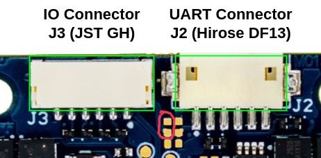
@tonygurney , I am assuming that you are using the ESC hardware version M0134 (you can confirm using
voxl-esc scantool.Here is the datasheet for M0134.
https://docs.modalai.com/modal-esc-datasheet/This ESC has an option (via installing a 0 ohm resistor) to provide 3.3V to pin 1 of J3. This is the same voltage that is used for the MCUs that run on the ESC and should be used with caution (if this voltage rail is brought down by overloading, the ESC will shut down). Please see image below that shows where 0 ohm resistor should be (carefully) installed to enable 3.3V on pin1 of J3 (marked in red)
If you actually wanted 5V (VAUX), that is available on the other side of the board via two test points at the edge of the board. This voltage rail is provided by a separate switching regulator. See the following section : https://docs.modalai.com/modal-esc-datasheet/#neopixel-led-support
If you REALLY need 5V to be present on pin1 of J3, then you can add a small wire jumper from the VAUX test point directly to the pin1 of J3 (which is marked with a white dot). This pin 1 of J3 is normally disconnected. Please only do this if you are comfortable performing this type of soldering and we cannot guarantee the results :).
Alex
Hello! It looks like you're interested in this conversation, but you don't have an account yet.
Getting fed up of having to scroll through the same posts each visit? When you register for an account, you'll always come back to exactly where you were before, and choose to be notified of new replies (either via email, or push notification). You'll also be able to save bookmarks and upvote posts to show your appreciation to other community members.
With your input, this post could be even better 💗
Register Login