12V Output Option for Power Module v3
-
Hello,
I was wondering if you could provide documentation on what components to swap out on the stock power module to convert the 5VDC to 12VDC? I have a few extras and wanted to rework the PCBA rather than purchase a new one is possible?
From a previous post from @Vinny I see that you mentioned "We have already configured and tested 12V versions of our power module as an FYI.
Thank you,
Blue -
Hi @blue
Sure, please give me till tomorrow and I can communicate some details (and risks) if you wanted to change the power module on your own.
Thanks! -
Hi @blue
So, first a few cautions about the 12V power module vs the 5V module:- Please remove the 4-pin Molex should you modify boards on your own. This is to ensure there are no accidental insertions from that 4-pin Molex using MCBL-00001 into a Voxl, Voxl-Flight, or Voxl 2. You will destroy your Voxl or Voxl-Flight. Voxl 2 has protections that will not allow it to turn ON should 12V be used instead of 5V, and you'll see a very bright RED LED for DS1: https://docs.modalai.com/voxl2-leds/
We actually do not sell the 12V version, but if we did, we would have that Molex connector removed. We only use it internally. - No warranties will be honored for modified CCAs, all soldering is done at your own risk
- The Power Modules require a LOT of heat to remove the components connected to GND. Use a very good soldering iron with good tips. Use flux as well, and our solder is Lead Free, so more heat is typically required for good shiny results.
- The voltage setting resistors use high values. Therefore, any flux residue left from soldering will impact the resistance values. It is imperative you use no-clean flux or if not, be sure you give the areas soldered a very good cleaning with alcohol afterwards. As part of this, be sure you test the result first, using a load box for a few amps to be sure it is stable. We use 3A in our factory test on every module sold.
- Use 1% resistors for optimal accuracy.
OK, with that out of the way, to convert 5V to 12V, you need to change two resistors. Both changes are required to match performance we designed and tested to.
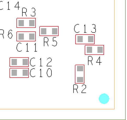
- R5 (this is connected to GND on one side) is an 0402 and needs to be changed to 86.6K.
- R4 (this is connected to GND on one side) is an 0402 and needs to be changed to 27.4K.
The values are exact. Do not use "something close" like 87.5K or 85.6K. Use 86.6K and 27.4K as noted.
Here is an ASSY view of the bottom side of the module, both R4 and R5 are noted in Silkscreen as well:

Hope this helps!
- Please remove the 4-pin Molex should you modify boards on your own. This is to ensure there are no accidental insertions from that 4-pin Molex using MCBL-00001 into a Voxl, Voxl-Flight, or Voxl 2. You will destroy your Voxl or Voxl-Flight. Voxl 2 has protections that will not allow it to turn ON should 12V be used instead of 5V, and you'll see a very bright RED LED for DS1: https://docs.modalai.com/voxl2-leds/
-
@Vinny thank you so much for the thorough and punctual response!
I will give this rework a shot per your instruction and report back if I have any issues.