RC input Voxl2 IO
-
We have received your IO Board, and will be using it solely to use the graupner radio and receiver.
IO board led lights show normal running mode, and the radio is bound to the receiver.
I cant see any RC input in QGC and 0 radio channels detected. There isnt a lot of info on setup of the IO board, am I missing something?
-
Hi @McMason ,
With graupner, it has generally not required setup, and if the LED is blinking blue on the VOXL2 IO board, then comms are working.
Can you confirm you are using J3 (likely the black JST connector)?
One way to troubleshoot that I use is as follows:
https://docs.modalai.com/voxl-px4-developer-guide/#how-to-access-the-px4-shell-pxhOnce you are running in the interactive shell, you can try:
qshell px4io status
and
px4-listener input_rc -
Hi Devteam, I'd like to echo this issue, as I'm having it too:
I'm using the R9SX FrSky receiver with S.BUS output, hence I thought J2 is the appropriate connection. I've confirmed the receiver is bound and receiving the signal, and the blue PX4IO light is blinking correctly. I've tried both J2 and J3, but no dice. "qshell px4io status" in my case seems to indicate no RC connection is active, so the breakdown is likely either in how the signal is getting into the PX4IO or a setting with the PX4 rc_input "module" running in the PX4 stack perhaps?
-
Hi Devteam, I'd like to echo this issue, as I'm having it too:
I'm using the R9SX FrSky receiver with S.BUS output, hence I thought J2 is the appropriate connection. I've confirmed the receiver is bound and receiving the signal, and the blue PX4IO light is blinking correctly. I've tried both J2 and J3, but no dice. "qshell px4io status" in my case seems to indicate no RC connection is active, so the breakdown is likely either in how the signal is getting into the PX4IO or a setting with the PX4 rc_input "module" running in the PX4 stack perhaps?
@JoeC BTW, also, please check possible conflicting info between these wiki pages:
1.) https://docs.modalai.com/voxl2-io-datasheet/ :The "Overview" image seems to suggest S.BUS is J2, while the "Connector Callouts" suggests S.BUS is J3.
2.) https://docs.modalai.com/voxl2-io-user-guide/: The "RC Connections" section here shows J3 as S.BUS.
I'm thinking J3 is the correct one for S.BUS inputs, given your response about the Graupner S.BUS being the black connector.
-Joe
-
@JoeC BTW, also, please check possible conflicting info between these wiki pages:
1.) https://docs.modalai.com/voxl2-io-datasheet/ :The "Overview" image seems to suggest S.BUS is J2, while the "Connector Callouts" suggests S.BUS is J3.
2.) https://docs.modalai.com/voxl2-io-user-guide/: The "RC Connections" section here shows J3 as S.BUS.
I'm thinking J3 is the correct one for S.BUS inputs, given your response about the Graupner S.BUS being the black connector.
-Joe
One more update:
Possible problem 1: The FrSky S.BUS output is normally LOW and goes HIGH with data (does it need to be inverted?) Attached a file showing this.
 )
)
Possible problem 2: I found that I see the receiver S.BUS output signal with an o-scope when NOT connected also to pin 3 SBUS_INPUT_INV of the black connector. Upon connecting the S.BUS output to this pin, the voltage stays low, as if pin 3 on the PX4IO is pulling it down. -
Hi @modaltb and @Adrian-Hidalgo, I wanted to follow up on this particular topic with the PX4IO board. I've confirmed that the S.BUS confirms to normal S.BUS parameters (a rather odd exactly 100 kbps baud rate, even parity, and 2 stop bits). The main problem is the S.BUS input pin on the PX4IO board, when connected up to the receiver output, is pulled LOW, hence the signal disappears. I think this is why it's not working correctly most likely. I'm not sure how to verify if this is a hardware or firmware issue? Any thoughts?
Secondly, I could start trying to play around with the firmware, but I just needed a bit more clarity on how to update. This document, https://docs.modalai.com/voxl2-io-firmware/ ,
suggests to:
"
FLASH
Write the 60kb application to 0x08001000
"
Do I need to purchase a JTAG or something to write the firmware to specific registers? I'm sorry to say I'm not sure how to actually do this. Thanks!-Joe
-
@JoeC ,
Sorry for the lag here as I failed to respond!!! If it's easier perhaps we can do a phone call to work through items here.
We've tested the SBUS interface with Graupner radios with success, I'm not entirely sure what's going on, I will have to get a HW setup for that and put a scope on there and see what's up.
For flashing....
- for HW, we use use: https://www.st.com/en/development-tools/st-link-v2.html
- then we use
STM32_Programmer_CLI
Here's the script I use to install this tool on Ubuntu for reference. You will need to download these files from ST:
#!/bin/bash

ST_LINK_ZIP=en.stm32cubeprg-lin_v2-7-0.zip
ST_LINK_PATCH_ZIP=en.stsw-link007_V2-38-27.zip

ST_LINK_EXE=SetupSTM32CubeProgrammer-2.7.0.linux
ST_LINK_PATCH_DIR=stsw-link007

if ! [[ -f "${ST_LINK_ZIP}" ]]; then
    echo "[ERROR] Missing file: ${ST_LINK_ZIP}"
    exit 1
fi
if ! [[ -f "${ST_LINK_PATCH_ZIP}" ]]; then
    echo "[ERROR] Missing file: ${ST_LINK_PATCH_ZIP}"
    exit 1
fi

echo "[INFO] Unzipping: ${ST_LINK_ZIP}"
sleep 1
if ! [[ -f "${ST_LINK_EXE}" ]]; then
    unzip "${ST_LINK_ZIP}"
fi

echo "[INFO] Unzipping: ${ST_LINK_PATCH_ZIP}"
sleep 1
if ! [[ -d "${ST_LINK_PATCH_DIR}" ]]; then
    unzip "${ST_LINK_PATCH_ZIP}"
fi

echo "[INFO] setting up udev rules"
sudo dpkg -i "${ST_LINK_PATCH_DIR}/AllPlatforms/StlinkRulesFilesForLinux/st-stlink-udev-rules-1.0.3-1-linux-all.deb"
echo "[INFO] reloading udev rules"
sudo udevadm control --reload-rules && udevadm trigger

echo "[INFO] Installing STLink"
sleep 1
./"${ST_LINK_EXE}"

echo "[INFO] Creating symbolic link"
sudo ln -s ~/STMicroelectronics/STM32Cube/STM32CubeProgrammer/bin/STM32_Programmer_CLI /usr/local/bin/STM32_Programmer_CLI

echo "[INFO] Testing"
STM32_Programmer_CLI -c port=SWD
Once that tool is installed, this is how I flash the binaries that are generated from the PX4 build:
BL_FW_FILE="000-test/data/2022-06-26-modalai_voxl2_io_bl.bin" BL_FLASH_START_ADDR="0x8000000" APP_FW_FILE="000-test/data/v1.11.4-0.0.2-modalai_voxl2io-v2.bin" APP_FLASH_START_ADDR="0x08001000" if ! [ -f "${BL_FW_FILE}" ]; then exit 10 fi if ! [ -f "${APP_FW_FILE}" ]; then exit 11 fi echo "erasing..." sleep 1 STM32_Programmer_CLI -c port=SWD -e all echo "programming bootloader..." sleep 1 STM32_Programmer_CLI -c port=SWD -w "${BL_FW_FILE}" "${BL_FLASH_START_ADDR}" -v echo "programming application..." sleep 1 STM32_Programmer_CLI -c port=SWD -w "${APP_FW_FILE}" "${APP_FLASH_START_ADDR}" -v echo "resetting..." sleep 1 STM32_Programmer_CLI -c port=SWD -hardRst -
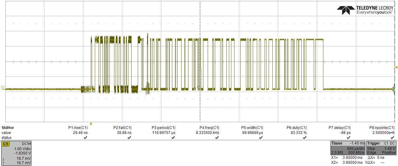
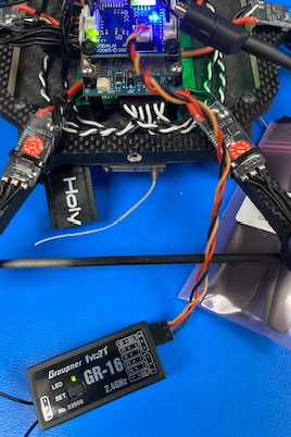
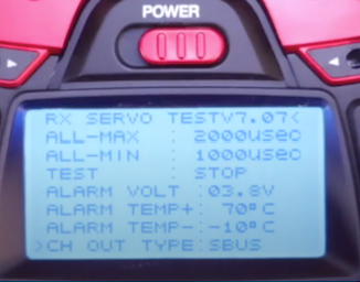
Hey Joe, we're going to chat tomorrow in person, but doing my homework today in prep. I have similar plot to you when using our Graupner GR-16 receiver (with mz-12 pro transmitter).
I'm using voxl2_platform_0.9.
Using J3 on the VOXL2IO:
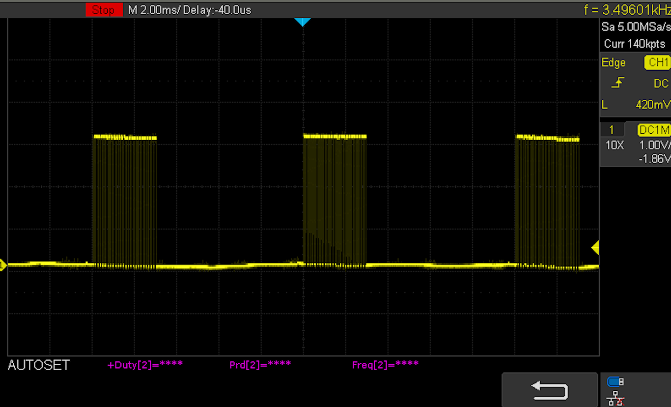
Here's my scope readings (1V per div):
And from QGC UI, I get channels:
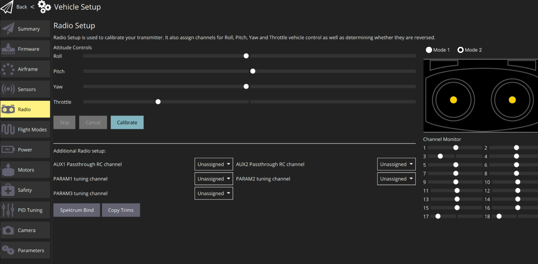
I have to run voxl-px4 manually to access these following commands, but once doing that, we can check some status with
qshell px4io status:... INFO [muorb] SLPI: 18 raw R/C inputs INFO [muorb] SLPI: 1913 INFO [muorb] SLPI: 1115 INFO [muorb] SLPI: 1115 INFO [muorb] SLPI: 1913 INFO [muorb] SLPI: 1514 INFO [muorb] SLPI: 1514 INFO [muorb] SLPI: 1514 INFO [muorb] SLPI: 1514 INFO [muorb] SLPI: 1514 INFO [muorb] SLPI: 1514 INFO [muorb] SLPI: 1514 INFO [muorb] SLPI: 1514 INFO [muorb] SLPI: 1514 INFO [muorb] SLPI: 1514 INFO [muorb] SLPI: 1514 INFO [muorb] SLPI: 1514 INFO [muorb] SLPI: 998 INFO [muorb] SLPI: 998We can kick off from this point tomorrow and see what's up.
Thanks!
-
Hey Joe, we're going to chat tomorrow in person, but doing my homework today in prep. I have similar plot to you when using our Graupner GR-16 receiver (with mz-12 pro transmitter).
I'm using voxl2_platform_0.9.
Using J3 on the VOXL2IO:
Here's my scope readings (1V per div):
And from QGC UI, I get channels:
I have to run voxl-px4 manually to access these following commands, but once doing that, we can check some status with
qshell px4io status:... INFO [muorb] SLPI: 18 raw R/C inputs INFO [muorb] SLPI: 1913 INFO [muorb] SLPI: 1115 INFO [muorb] SLPI: 1115 INFO [muorb] SLPI: 1913 INFO [muorb] SLPI: 1514 INFO [muorb] SLPI: 1514 INFO [muorb] SLPI: 1514 INFO [muorb] SLPI: 1514 INFO [muorb] SLPI: 1514 INFO [muorb] SLPI: 1514 INFO [muorb] SLPI: 1514 INFO [muorb] SLPI: 1514 INFO [muorb] SLPI: 1514 INFO [muorb] SLPI: 1514 INFO [muorb] SLPI: 1514 INFO [muorb] SLPI: 1514 INFO [muorb] SLPI: 998 INFO [muorb] SLPI: 998We can kick off from this point tomorrow and see what's up.
Thanks!
@modaltb Hi Travis, I'm planning on taking another look at this soon, however I've been diverted a bit trying to get a Graupner GR-16 (the type of Graupner model you typically ship as an option) to output S.BUS. I wanted to have a second model to test against in addition to the FrSKY R9SX. Thing is, for the life of me, I don't see S.BUS as an option in the Graupner receiver menu. Just 'SAME', 'ONCE', 'SUM0', and SUMD3, and SUMD(OF/HD/FS)(<0-16 number). Sorry to sidetrack our debugging a bit, but thought you might be able to confirm the GR-16 can actually output S.BUS?
-Joe -
Here's a setup video we use for Flight Core that should help.
- YouTube
Enjoy the videos and music you love, upload original content, and share it all with friends, family, and the world on YouTube.

(www.youtube.com)
This is where he's plugging it in:
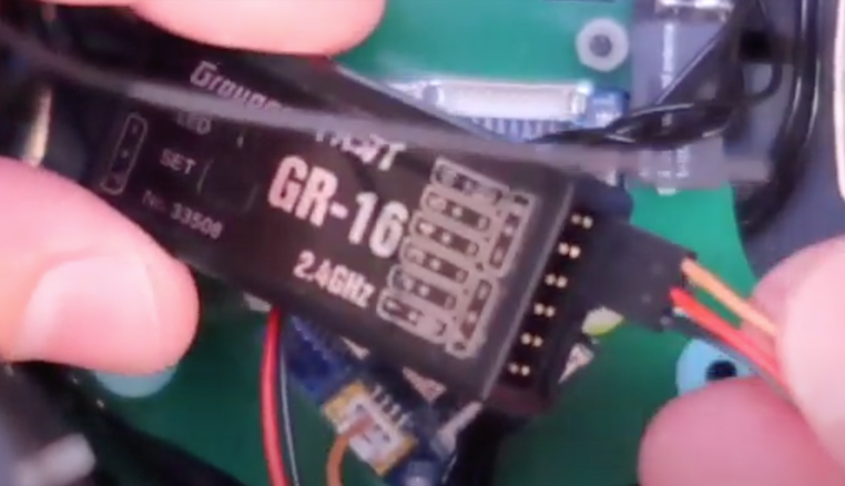
towards the end of the video, it shows how to setup SBUS:
-
Hi @modaltb Travis, it took me a bit to have time to get back to this, but I've confirmed the problem. There was a short between input and ground in the small 4-pin GH connector I was using to connect to the VOXL2 IO board. Given I just found that laying around, I should have caught this earlier. Thanks for your help! I can confirm that the PX4IO app does see the R9SX input now. I'll also refer to your other post soon about trying to setup the Graupner GR-16 as I'll be moving to that this summer.
Hello! It looks like you're interested in this conversation, but you don't have an account yet.
Getting fed up of having to scroll through the same posts each visit? When you register for an account, you'll always come back to exactly where you were before, and choose to be notified of new replies (either via email, or push notification). You'll also be able to save bookmarks and upvote posts to show your appreciation to other community members.
With your input, this post could be even better 💗
Register Login